Terminal symbol Terminal name Description
P1 DC reactor connection terminal Remove the short-circuit bar between the terminals
P1 and P(+), and connect an optional DC reactor.
P(+)
P(+) Braking resistor connection termi-
nal
Connect an optional braking resistor (if a braking
torque is required).
DB
P(+) Regenerative braking unit con-
nection terminal
Connect optional regenerative braking units (if a
braking torque is required and that produced by the
built-in braking circuit is insuf
ficient).
N(-)
R0, T0 Control power supply auxiliary in-
put
To hold a batch alarm signal when the protection
function is activated even if the main power supply
of the inverter is cut off or to display the Digital Op-
erator at all times, connect these terminals to the
power supply (at a capacity of 1.85 kW or more, for
details, refer to 2-3-4 W
iring for Main Circuit Termi-
nals on page 2-15).
G
Ground terminal This is the ground terminal. Connect this terminal to
the ground.
200-V class should be connected under type-D
grounding conditions; 400-V class should be con-
nected under type-C grounding conditions.
2-3-3
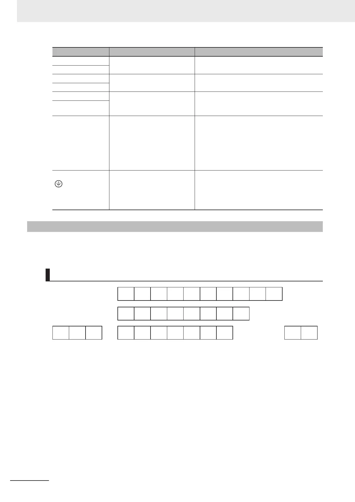
Arrangement and Function of Control Circuit Terminal Block
The table below shows the arrangement of the control circuit terminal block, and description and spec-
ifications of each terminal.
Control Circuit Terminal Block
AI2 PTC +10 AI1 AIC DI1 DI2 DI3 DI4 DI5
AO
DO1 DO2 DOC DI6 DI7 DIC +24
ROA ROB ROC SP SN PIA PIB PIZ DIC +24 SF1 SF2
2 Design
2-12
M1 Series Standard Type User's Manual (I669)

 Loading...


