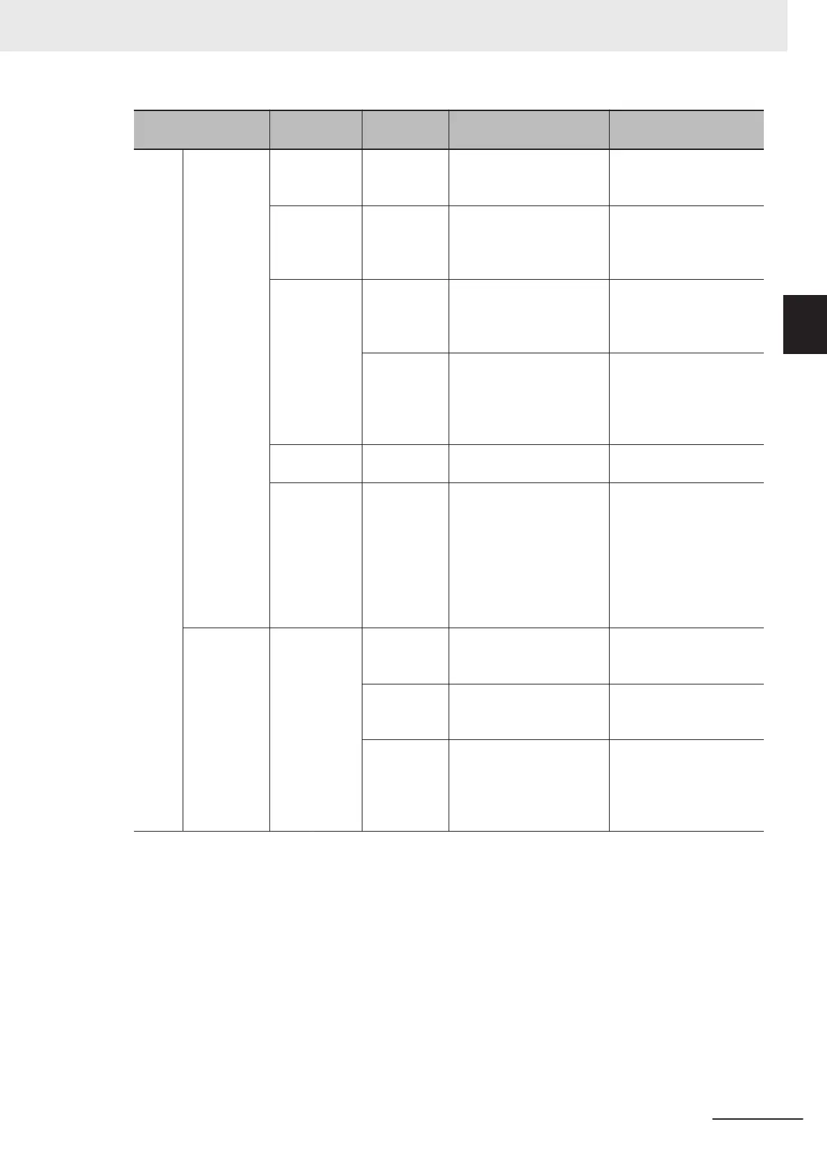
Item
Terminal
symbol
Terminal
name
Description Specifications
Ana-
log
Input +10 Power sup-
ply for ana-
log input
This is a 10 VDC power
supply for the AI1 terminal.
Maximum allowable cur-
rent: 10 mA
AI1 Analog volt-
age input
This is a -10 to 10 VDC
analog voltage input.
Input impedance: 22 kΩ
Allowable input voltage
range:
-15 to 10 VDC
AI2 (AII) Analog cur-
rent input
This is a 4 to 20 mA DC
analog current input.
Input impedance:
250 Ω
Allowable input range:
0 to 30 mA
(AIV)
Analog volt-
age input
This is a 0 to 10 VDC ana-
log voltage input.
Input impedance:
22 kΩ
Allowable input voltage
range:
-15 to 10 VDC
AIC Analog input
common
Common terminal for the
analog input.
PTC External
thermistor in-
put
Connect an external ther-
mistor between the PTC
and the AIC, and when an
abnormal temperature is
reached, an inverter trip is
generated. (Set the inver-
ter trip level at parameter
H27.)
PTC type
Output AO (AOV) Multi-function
analog out-
put (V
oltage)
This terminal can output
the specified signal as a 0
to 10 VDC voltage signal.
Input impedance:
Approx. 5 kΩ
(AOI)
Multi-function
analog out-
put (Current)
This terminal can output
the specified signal as a 4
to 20 mA current signal.
Input impedance:
Approx. 500 Ω
(PO)
Multi-function
analog out-
put (Pulse
output)
Output a pulse. Output pulse: 32 kHz
max.
Output voltage: 11 VDC
Allowable current: 2 mA
max.
2 Design
2-13
M1 Series Standard Type User's Manual (I669)
2-3 Wiring
2
2-3-3 Arrangement and Function of Control Circuit Terminal Block

 Loading...


