1-2
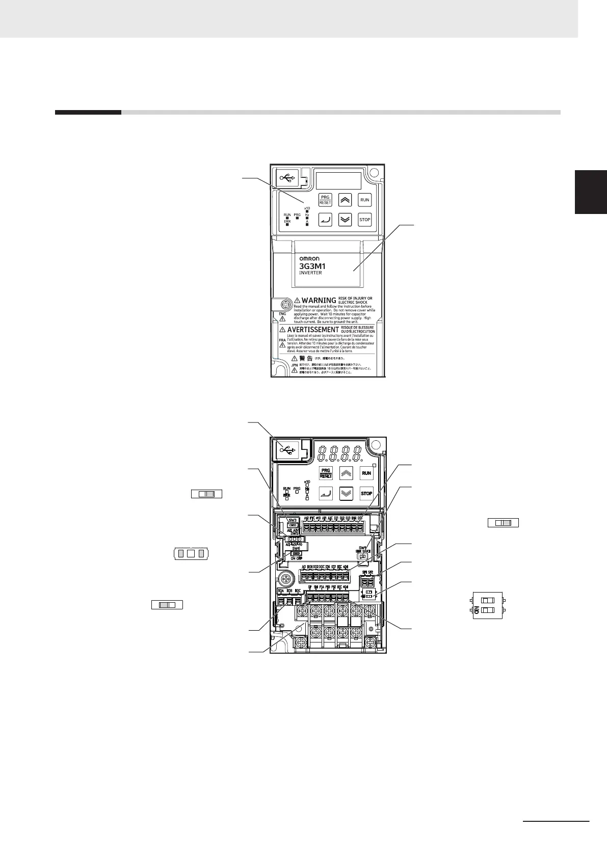
Appearance and Part Names
The following shows the front view when the product is unpacked.
(An example of 3G3M1-AB001/AB002/AB004/AB007/A2001/A2002/A2004/A2007)
Operator
Terminal block cover
Open the terminal block cover to wire the main circuit terminal block and the control circuit terminal
block.
Control circuit terminal block A
Digital input sink/
source selector switch (SW1)
Control circuit terminal block B
Safety input terminal block
Safety function selector switch (SW9)
Control circuit terminal block C
USB connector
(Micro-B)
Analog input
selector switch (SW3)
Analog output selector switch (SW5)
Terminating resistor
selector switch (SW6)
Relay output terminal block
Main circuit terminal block
(Factory default)
SOURCE
SINK
(Factory default)
AII
(Factory default)
AOV
PO
AOI
AIV
(Factory default)
OFF
O
N
OFFON
1 Overview
1-7
M1 Series Standard Type User's Manual (I669)
1-2 Appearance and Part Names
1

 Loading...


