Analog current
input [AI1]
ON
OFF
SW3
4 to 20 mA/
0 to 20 mA selection
(AIV)
(AII)
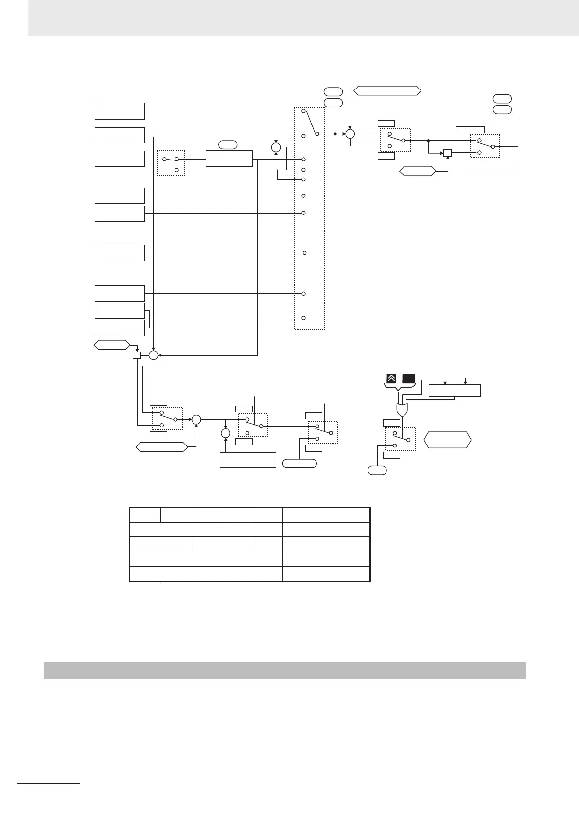
C40
2nd Frequency Reference Selection
C30
USB connector
2nd control
“SET”
ON
OFF
Forced terminal
block function “F-TM”
ON
OFF
Addition/
subtraction “ADD”
ON
OFF
Forced operator
function “OPE”
ON
OFF
(E134) Frequency
Addition Amount
+
+
C99/E109
C30
Jogging frequency
Frequency
reference
[PIA]
[PIB]
The presence/absence of the pulse train command depends on the combination of the following parameter settings.
F01 C30 E131 E132 E119
Pulse train command
Set frequency
45 PID feedback
3 Without
Without
Other than the above
Ignore
Any one is 5
Any one is 12
Any one is 13
Other than the above
Operator
[E48]
1st Frequency Reference Selection
F01
+
+
Frequency auxiliary setting 1
Other than below
C30
F01
F01/C30
= 1, 2, 3, 5, 10, 12
×
Analog current
input [AI2]
+
+
UP/DOWN control
Pattern operation
+
+
×
Ratio value
Ratio value
+
+
Frequency auxiliary setting 2
STOP
+
Forward/Reverse
JOG judgment
Forward JOG
(FJOG)
Reverse JOG
(RJOG)
Jogging
(JG)
*1
*3
*4
Modbus
communication
Calculation result
*3
*2
0.8
1
2
3
5
7
10
12
13
14
2nd Frequency Reference Selection
1st Frequency Reference Selection
1st Frequency Reference/
1st Multi-step Frequency Reference 0/
2nd Frequency Reference/
2nd Multi-step Frequency Reference 0
*1. Auxiliary frequency setting 1 is set by setting 1 to Extended functions (E61/E62/E63).
*2. Auxiliary frequency setting 2 is set by setting 2 to Extended functions (E61/E62/E63).
*3. Ratio value is set by setting 6 to Extended functions (E61/E62/E63).
*4. For details on the result of logical operation, refer to 7-9-8 Frequency Calculation Function on page 7-118
.
5-5-2
Frequency Limit
• Use this function to set the upper and lower limits of the output frequency. The set limits will be ap-
plied if the input frequency reference is beyond the upper/lower limit(s).
•
Be sure to set so that the Frequency Upper Limit (F15/E117) is greater than the Frequency Lower
Limit (F16/E1
18).
• Set the lower limit so that it does not reach or exceed Maximum Output Frequency (F03/A01).
• When 0 Hz is set to the upper limit, operation is limited to 0 Hz and disabled.
5 Basic Settings
5-32
M1 Series Standard Type User's Manual (I669)

 Loading...


