4-1-2
Parameter W (Monitor 2)
Parameter
No.
Function name Monitor or Data Range
Default
data
Setting
during
RUN
Unit
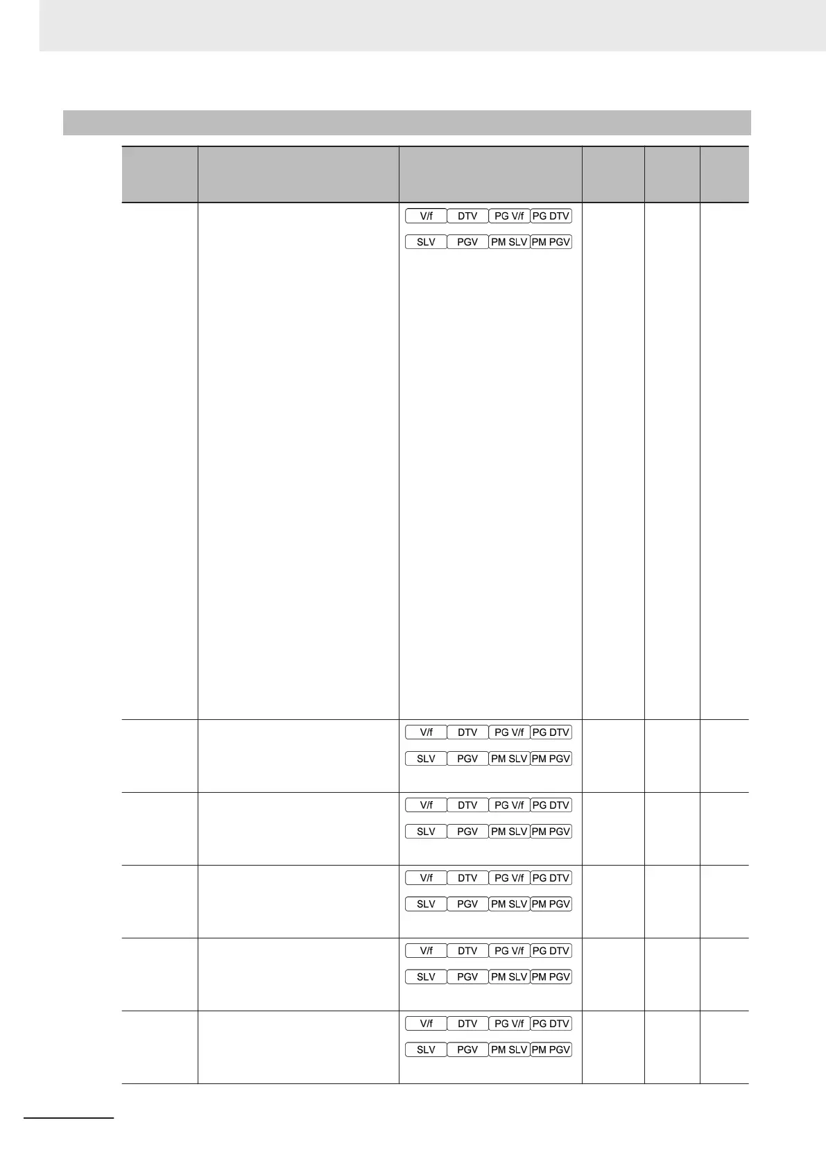
W01 Running Status 1 Monitor
Bit15: BUSY (During Parame-
ter code data writing)
Bit14: -
Bit13: -
Bit12: RL (Communications ef-
fective)
Bit11: ALM (Alarm relay)
Bit10: DEC (During decelera-
tion)
Bit9: ACC (During accelera-
tion)
Bit8: IL (During current limit-
ing)
Bit7: VL (During voltage limit-
ing)
Bit6: TL (Torque limiting)
Bit5: NUV (Main circuit DC
voltage established)
Bit4: BRK (During braking)
Bit3: INT (Inverter shut down)
Bit2: EXT (During DC braking
or during pre-exciting)
Bit1: REV (During reverse op-
eration)
Bit0: FWD (During forward op-
eration)
0
- -
W02 Frequency Reference Monitor
0.00 to 655.35
0 - Hz
W03
Output Frequency Monitor before
Slip Compensation
0.00 to 655.35 Hz
0 - Hz
W04
Output Frequency after Slip Com-
pensation
0.00 to 655.35
0 - Hz
W05 Output Current Monitor
0.00 to 99.99 A
0 - A
W06 Output Voltage Monitor
0.0 to 1000.0 V
0 - V
4 Parameter List
4-30
M1 Series Standard Type User's Manual (I669)

 Loading...


