+24
DI1 to DI7
DIC
Output unit Inverter
Photocoupler
Sink
Source
24 VDC
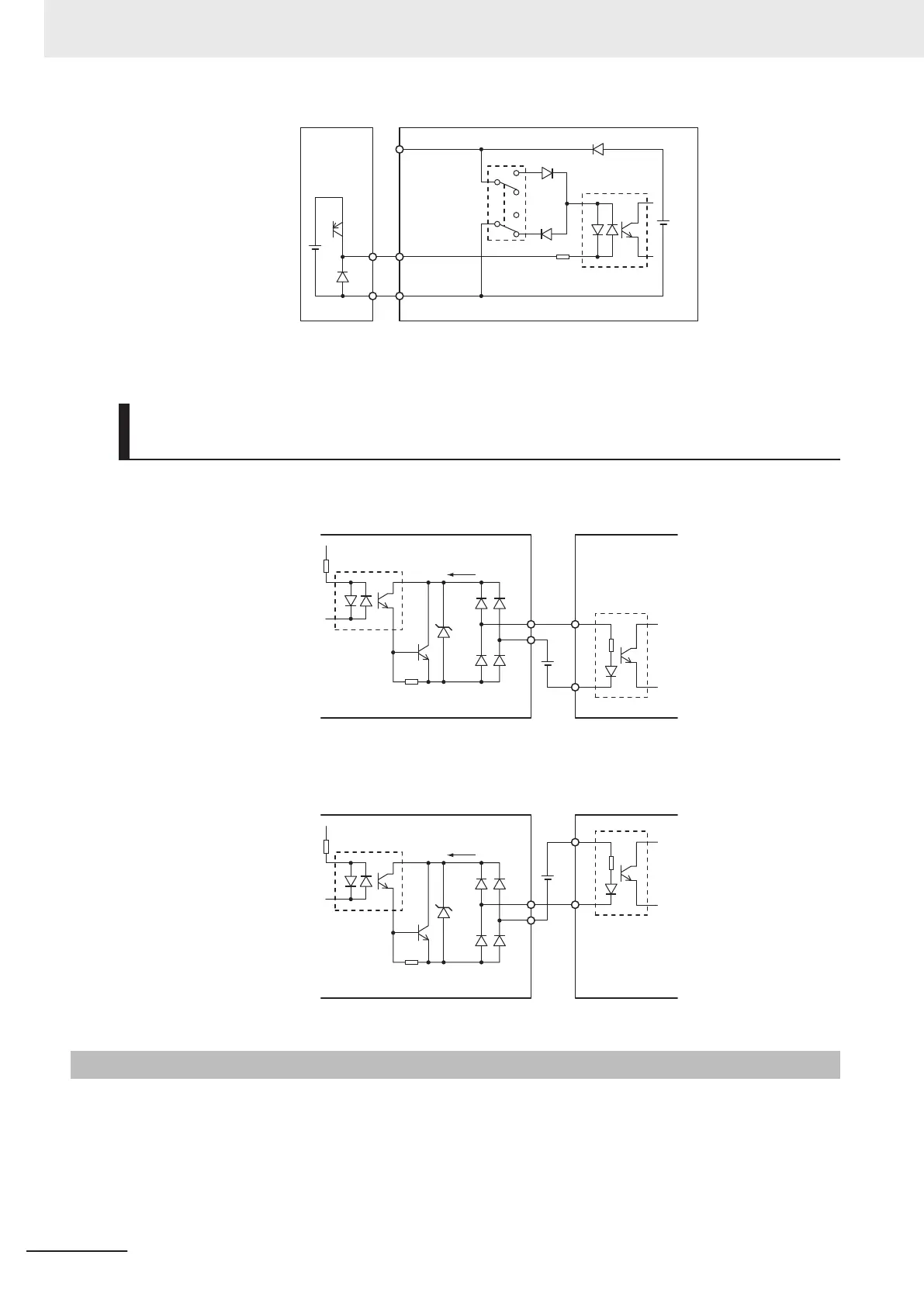
Multifunction Output Terminals and Programmable Controller Con-
nection
Sink logic
55 to
70 V
DOC
DO1
DO2
Input unitInverter
Photocoupler
Sink input
Current flow
24 VDC
Source logic
55 to
70 V
DOC
DO1
DO2
Input unitInverter
Photocoupler
Source input
Current flow
24 VDC
2-3-6
Recommended Encoder and Its Wiring
For the pulse train input function of the 3G3M1 Series inverter, be sure to use a complementary output
type encoder.
In addition, for encoder cable connection, always use a shielded cable and connect it to the DIC termi-
nal of the inverter’
s control circuit terminal block.
If an open collector output encoder is used, the inverter may not recognize the rotation in the forward
or reverse direction. This is because, as the length of the encoder cable increases, its stray
2 Design
2-54
M1 Series Standard Type User's Manual (I669)

 Loading...


