capacitance becomes larger, which causes the inverter to falsely recognize the crosstalk signal from
the encoder.
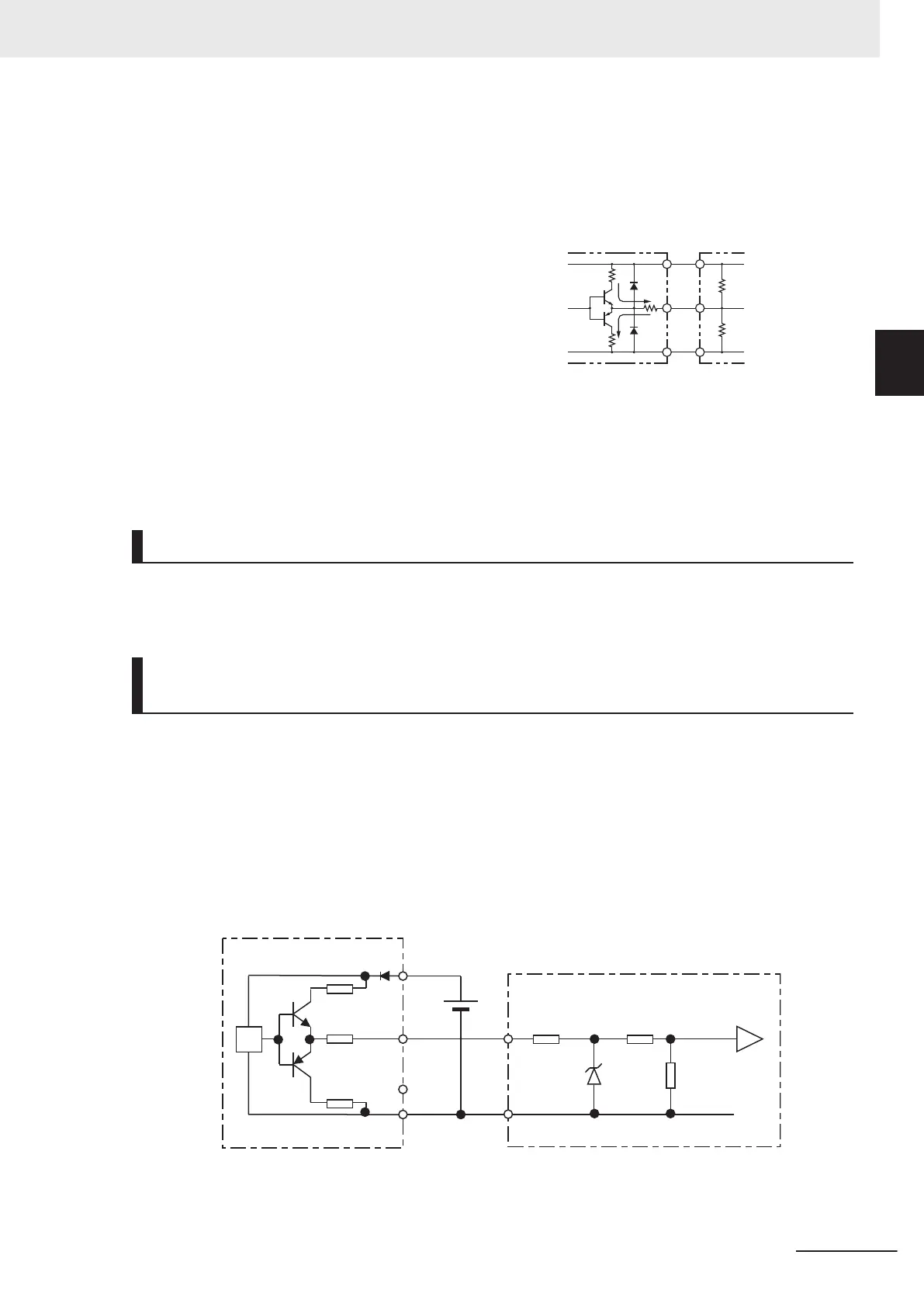
Complementary output
Complementary output is a method of outputting via
two transistors.
The wiring is connected to the 0 V side when output
is ON and to the power supply side when output is
OFF
.
This design does not allow the wiring to be left open
(at high impedance) as in the case of open collector
output encoders.
Therefore, this provides a stable output from the en-
coder.
OUT
0V
E6C3-CWZ5GH
NPN
T
ransistor
PNP
Transistor
Power
supply
Signal
Recommended product
E6C3-CWZ5GH (Manufacturer: OMRON)
Encoder Input
For pulse train input, use the pulse train input PIA and PIB terminals of the control circuit terminals.
Be sure to use a complementary output type encoder.
Wiring for Phase A and B 90° Phase Difference Pulse Train (d14 = 2
or 3)
Connect the phase A and B 90° phase difference pulse train as shown in the diagram below.
• Connect the phase A signal to the pulse input PIA terminal and the phase B signal to the pulse train
input PIB terminal.
• The +24 V terminal of the inverter control circuit terminal block is for a 100 mA maximum 24 V pow-
er supply. This terminal can be used for the encoder power supply if the consumption current for the
input terminals in use and the encoder power supply is allowable. However, note that this terminal
must be isolated from any 24 V system power supply for other than the encoder and inverter.
7.5 Ω
24 Ω
7.5 Ω
1.68 kΩ
3.3 kΩ
2.2 kΩ
5.6V
External power supply PO: 5 to 24 V
(4.75 V min. to 28 V max.)
24-V power supply (Brown)
PO
Phase A (Black)
Phase B (White)
GND (Blue)
Complementary output
(E6C3-CWZ5GH)
PIA
PIB
2 Design
2-55
M1 Series Standard Type User's Manual (I669)
2-3 Wiring
2
2-3-6 Recommended Encoder and Its Wiring
 Loading...


