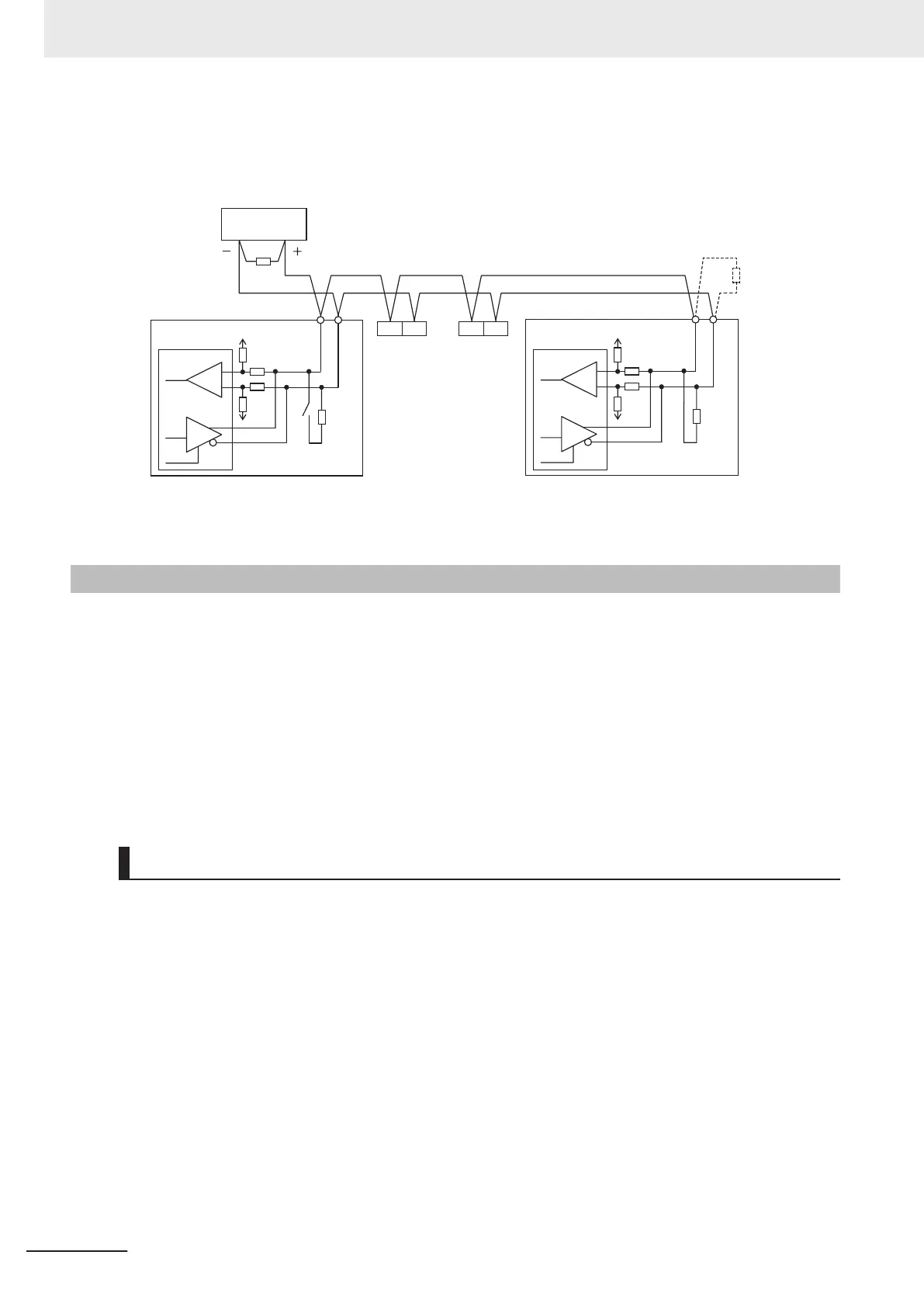
Selecting a terminating resistor appropriate to the cable impedance improves the terminating effect.
For this inverter, however, turning ON the terminating resistor selector switch enables the built-in termi-
nating resistor (1
12 Ω).
SN SP
SP
SN
SN SP
110
W
3G3M1 (No.2) 3G3M1 (No.3)
3G3M1 (No.1)
3G3M1 (No.n)
SP
SN
110
W
*1
External equipment
(Master)
*1. If the communications are unstable, install a terminating resistor appropriate to the impedance of the cable to
each cable end. The resistance of the terminating resistor built into this inverter is 110 Ω.
2-3-8
Safety Function
The safety function is designed so that the safety stop function of category 0 (uncontrolled stop) speci-
fied in IEC 60204-1 is used to meet the safety standards of PL-e under ISO 13849-1.
The safety input function allows the inverter output when current flows in both the terminals SF1 and
SF2.
When the safety input function is activated, in compliance with the above standards, the output tran-
sistor operation of the inverter
is stopped safely (by shutting of
f its output). As a result, the motor stops with free run.
For details, refer to 7-6 Safety Function
on page 7-69.
Note
This inverter meets ISO13849-1 PLc when the EDM function is disabled.
Safety Function Settings
To use the safety function, it must be set beforehand. By default, the safety function is disabled.
Use of the safety function is enabled by turning SW9 OFF.
Turn OFF both of the safety function selector switch SW9 when the inverter power supply is turned
OFF
. When using EDM output (safety monitor output), set “102: EDM (safety monitor)” at the multi-
function output terminal.
When the safety function is used→Both OFF
When the safety function is not used→Both ON
When only one is ON, the logic of the SF1 and SF2 signals no longer matches and this causes an
ECF alarm.
2 Design
2-58
M1 Series Standard Type User's Manual (I669)

 Loading...


