d14 data Pulse input method Remarks
2
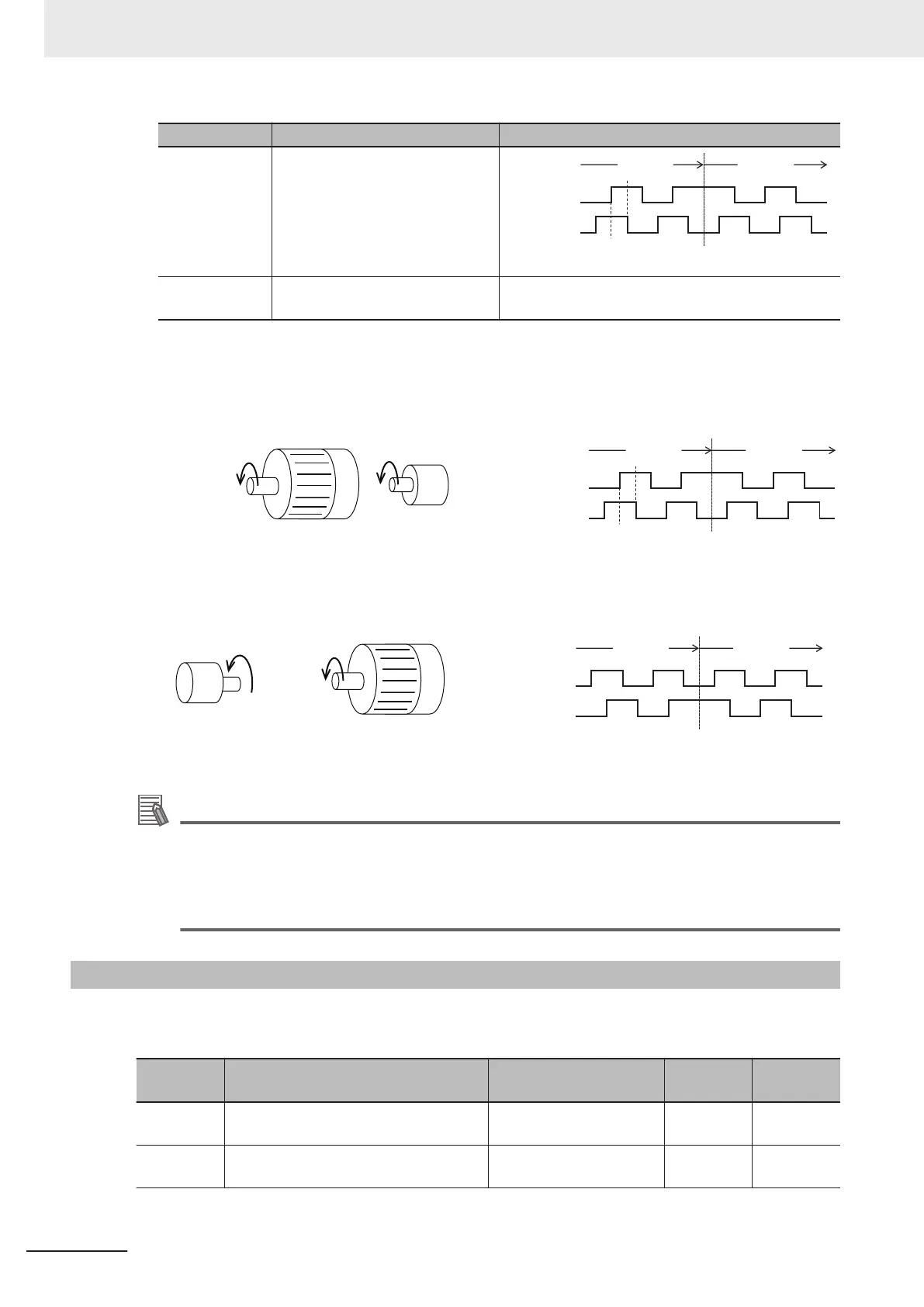
Quadrature A/B signal
(B phase lead)
Phase A input
Forward Reverse
Phase B input
Phase B lead Phase B delay
90°
3
Quadrature A/B signal
(A phase lead)
When d14 = 2, reverse rotation (A phase lead be-
comes forward rotation).
The counterclockwise direction (CCW) as viewed from the shaft side is taken as the forward rota-
tion direction of the motors. At this time, if the output pulse of the encoder is B phase lead, set “2:
Quadrature A/B signal (B phase lead)” at Input Terminal [PIA][PIB] Pulse Input Format Selection
(d14).
CCW: Forward
Motor Encoder
Phase A input
Forward Reverse
Phase B input
Phase B lead Phase B delay
90°
If the output pulse of the encoder is A phase lead, set “3: Quadrature A/B signal (A phase lead)” at
Input Terminal [PIA][PIB] Pulse Input Format Selection (d14).
CCW: Forward
MotorEncoder
Phase A input
Forward Reverse
Phase B input
Phase A lead Phase A delay
90°
Additional Information
In the case of a motor that complies with the IEC Standards, forward rotation causes the motor
to rotate clockwise (CW).
Either connect the output pulse of the encoder during forward (CW) rotation so that it becomes
B phase lead, or set Input Terminal [PIA][PIB] Pulse Input Format Selection (d14) to match the
output pulse of the encoder.
6-2-2
Protective Detection under V/f Control with Speed Feedback
In V/f control with speed feedback, the following protective detection functions can be used.
Use these functions according to your application.
Parameter
No.
Function name Data
Default da-
ta
Unit
d21
Speed Agreement / Speed Deviation Er-
ror Hysteresis Width
0.0 to 50.0 10.0 %
d22
Speed Agreement / Speed Deviation Er-
ror Detection Timer
0.00 to 10.00 0.50 s
6 Vector Control and Applied Functions
6-12
M1 Series Standard Type User's Manual (I669)

 Loading...


