5-4
RUN command
5-4-1
RUN Command Selection
Select the input method for the RUN command.
Parame-
ter No.
Function name Data
Default
data
Unit
F02
E102
1st RUN Command
Selection
2nd RUN Command
Selection
*1
0 to 5
0: Operator (Direction of rotation input: terminal
block)
1: External signal (FW or RV)
2: Operator (Forward rotation)
3: Operator (Reverse rotation)
4: RS-485 communication
5: Do not use
2 -
Related functions Input Terminal [DI6] Function Selection (E98), Input T
erminal [DI7] Func-
tion Selection (E99)
Refer to 5-9-1 Input Terminal Functions on page 5-51.
Operation command (S06)
*2
*1. To enable switching to the 1st and 2nd control, allocate “12: SET (2nd control)” to either of input terminal
[DI1] to [DI7].
*2. When “4: RS-485 communication” is selected at 1st RUN Command Selection (F02)/2nd RUN Command
Selection (E102), the FW command is executed by setting bit 0 of Operation command (S06) to ON, and the
RV command is executed by setting bit 1 to ON. These parameters are exclusively for reading and writing
via the RS-485 interface. These parameters are not displayed on the Operator. To check these parameters,
use Sysmac Studio.
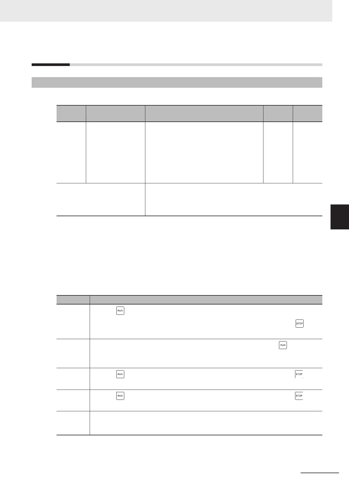
The operation method for data selected at 1st RUN Command Selection (F02)/2nd RUN Command
Selection (E102) is as follows.
Data Operation method
0
When the key on the Operator is pressed, forward rotation is performed when the FW termi-
nal turns ON. Reverse rotation is performed when the RV terminal turns ON. When the
key is
pressed, operation is stopped.
1
Forward rotation is performed when the FW terminal turns ON regardless of the
key on the
Operator. Reverse rotation is performed when the RV terminal turns ON. Operation stops when
both the FW and RV terminals are OFF or both are ON.
2
When the
key on the Operator is pressed, forward rotation is performed. When the key is
pressed, operation is stopped.
3
When the
key on the Operator is pressed, reverse rotation is performed. When the key is
pressed, operation is stopped.
4
When bit 00:FW in Operation command (S06) is turned ON via RS-485 communication, forward
rotation is performed. When bit 01:RV is turned ON, reverse rotation is performed. When both are
OFF or ON, operation is stopped.
• When “0: Operator (Direction of rotation input: terminal block)” and “1: External signal (Digital input)”
are selected at RUN Command Selection (F02/E102), allocate “98: FW (forward rotation)” and “99:
RV (reverse rotation)” to each of Input Terminal [DI6] Function Selection (E98) and Input Terminal
5 Basic Settings
5-25
M1 Series Standard Type User's Manual (I669)
5-4 RUN command
5
5-4-1 RUN Command Selection

 Loading...


