[DI7] Function Selection (E99). Operation stops when both the FW and RV terminals are ON or
OFF.
• When “1: External signal (Digital input)” is selected at RUN Command Selection (F02/E102), 3-wire
input is possible. Refer to 3-wire Input Function (FW
, STP, F/R) on page 5-56.
• The RUN command from the Operator can be forcibly enabled via input terminals. Refer to
7-7-2 Forced Operator Function (OPE) on page 7-75. The RUN command from an input terminal
can also be forcibly enabled via input terminals. Refer to 7-7-3 Forced Terminal Block Function (F-
TM) on page 7-75.
• When the inverter is outputting to the motor, operation is in progress and the RUN-LED lights. Lights
during deceleration after RUN command OFF. Goes out while the RUN command is ON at frequen-
cy reference 0 Hz as there is no output. When zero speed control is being executed, this lights as
the inverter outputs even when the frequency reference is 0 Hz.
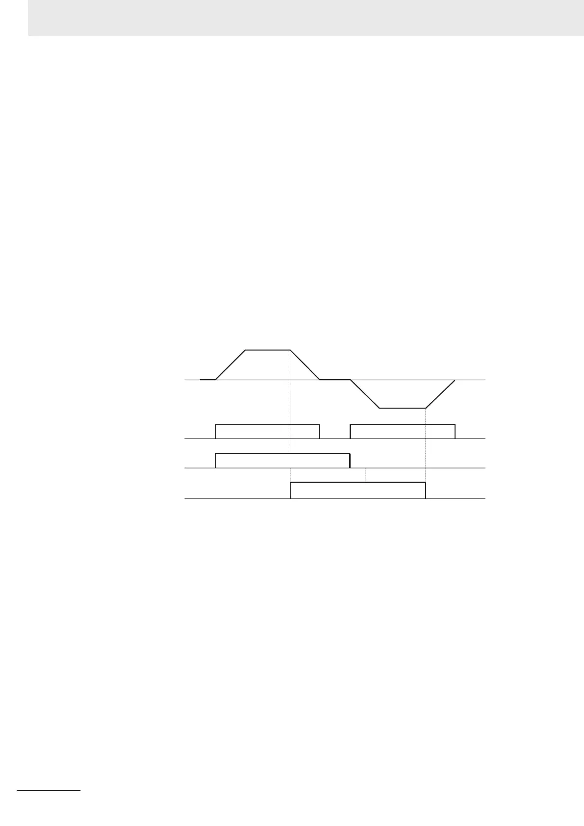
Operation example
• The following shows an example of operation by forward command FW input and reverse com-
mand RV input when “1: External signal (Digital input)” is selected at RUN Command Selection
(F02/E102).
Output frequency
ON ON
ON
ON
Forward
Reverse
RUN-LED
FW terminal
RV terminal
5 Basic Settings
5-26
M1 Series Standard Type User's Manual (I669)

 Loading...


