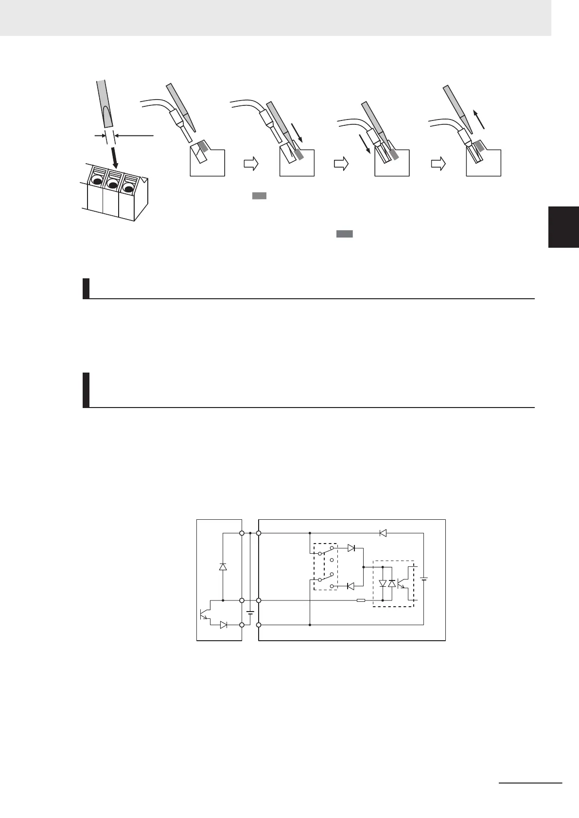
2.5mm
Insert the wire.
Remove the
flat-blade screwdriver
to clamp the wire.
Push in the shaded
portion with a
flat-blade screwdriver.
Note
To disconnect, pull out the wire with the shaded (
) portion pushed in with a flat-blade screwdriv-
er.
Selecting Input Control Logic
By factory default, the multifunction input terminals are set to sink logic (NPN).
To change the input control logic to source logic (PNP), switch SW1 on the control printed circuit board
to the SOURCE side.
Multifunction Input Terminals and Programmable Controller Con-
nection
Sink logic
On products not provided with a selector switch when an external power supply is used, DIC must
never be wired to the 0 V or SC terminal on the PLC to prevent a connection that will allow the
external power supply to be charged by the internal 24 VDC voltage of the inverter. When the inver-
ter malfunctions, for example, due to the voltage difference with the external power supply, review
the DIC connection destination.
+24
DI1 to DI7
DIC
Output unit Inverter
Photocoupler
Sink
Source
24 VDC
Source logic
With use by an external power supply using source logic, take care not to connect the 24 V termi-
nal to the external power supply or the PLC on the other side. A malfunction might arise due to the
voltage difference between the internal power supply and the external power supply.
2 Design
2-53
M1 Series Standard Type User's Manual (I669)
2-3 Wiring
2
2-3-5 Wiring for Control Circuit Terminals

 Loading...


