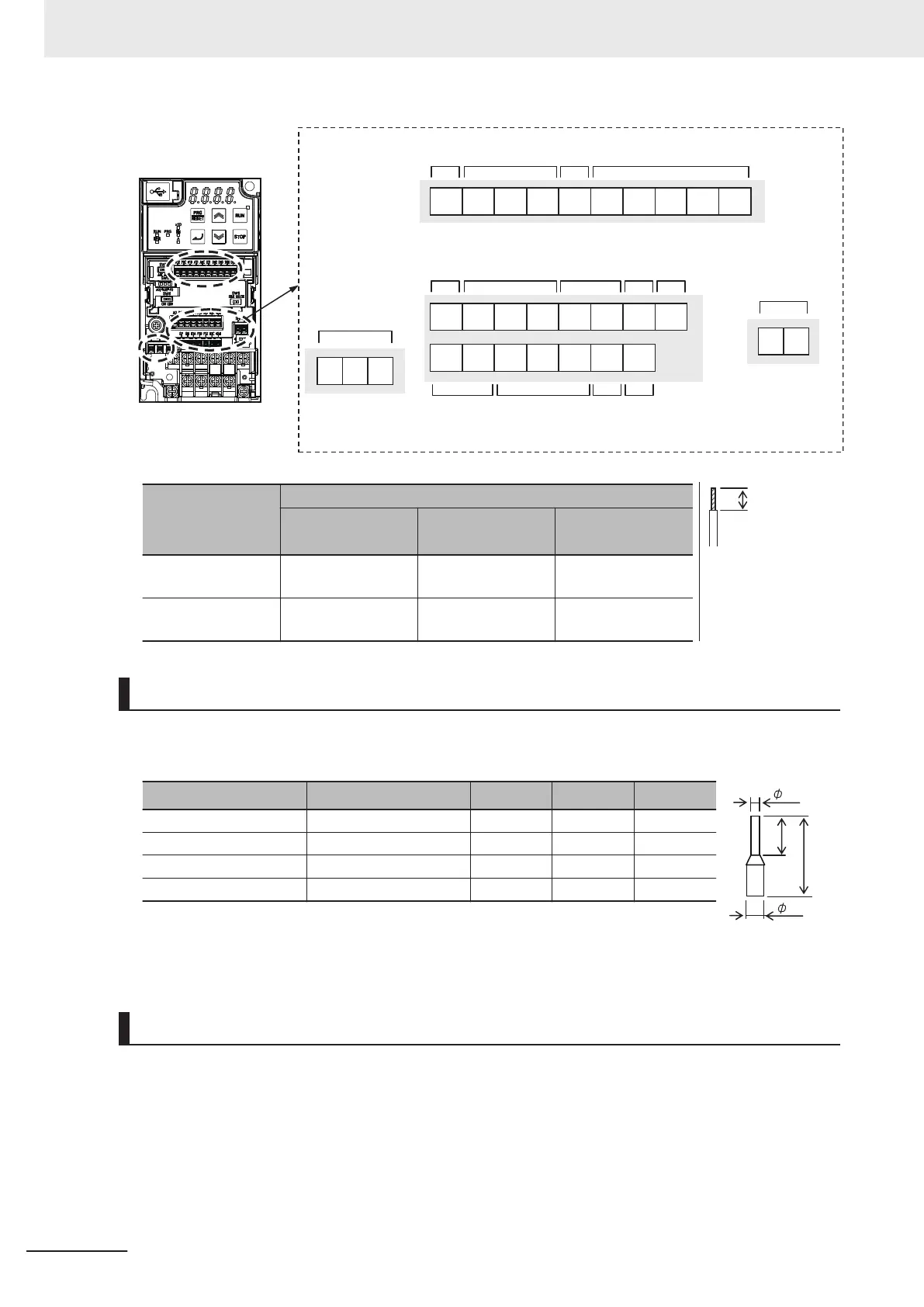
DIC +24PIB PIZPIASP SN
DI7 DIC +24DOC DI6DO2AO DO1
DI1 DI2 DI3 DI4 DI5AI1 AIC+10AI2 PTC
ROA ROB ROC
SF1 SF2
Analog input
and power supply
Relay output
Analog
output
Output
Communi-
cations
RS-485
Power
supply
Pulse input
Input
common
and power supply
Power
supply
Analog input and
power
supply
Input
Input
Analog
output
Input
common
Input
Applicable wire
Solid wire mm
2
(AWG)
Stranded wire
mm
2
(A
WG)
Ferrule mm
2
(A
WG)
Other than below 0.2 to 1.5
(AWG24 to 16)
0.2 to 1.0
(A
WG24 to 17)
0.25 to 0.75
(AWG24 to 18)
ROA/ROB/ROC
SF1/SF2
0.2 to 1.5
(AWG24 to 16)
0.2 to 1.0
(AWG24 to 17)
0.25 to 0.75
(AWG24 to 18)
8mm
Sheath strip length
should be approx.
8 mm for solid/
stranded wire
Recommended Terminal
To improve ease of wiring and reliability in connection, it is recommended to use ferrules with the fol-
lowing specifications for signal wires.
Wire size mm
2
(AWG) Ferrule type
*1
L [mm] ϕd [mm] ϕD [mm]
0.25 (24) AI 0.25-8YE 12.5 0.8 2.0
0.34 (22) AI 0.34-8TQ 12.5 0.8 2.0
0.5 (20) AI 0.5-8WH 14 1.1 2.5
0.75 (18) AI 0.75-8GY 14 1.3 2.8
*1.
Manufacturer: PHOENIX CONTACT
Crimping tool: CRIMPFOX 6
Wiring Method
1 Push in the orange colored portion of the control circuit terminal block with a flat-blade screw-
driver (blade width: 2.5 mm max.) to open the wire insertion hole.
2 With the flat-blade screwdriver pushed in, insert the wire or ferrule into the wire insertion
(round) hole.
3 Remove the flat-blade screwdriver to clamp the wire.
2 Design
2-52
M1 Series Standard Type User's Manual (I669)

 Loading...


