Cable length between inverter and motor
If the length of the cables between the inverter and the motor is long, consider how to address the
following problems.
• Voltage drop in output cables
As the cable length between the inverter and the motor increases, the resistance in the cables
becomes higher and accordingly the amount of voltage drop in the inverter output voltage be-
comes larger
. This causes a decrease in the voltage that is applied to the motor, which results in
a low output torque.
If the cables are long, take measures to reduce the resistance, for example, by selecting cables
whose wire diameter is larger than specified.
• Surge in long cables
If the cable length exceeds 20 m, a surge voltage (approx. 1200 V max. for 400-V class) may be
generated at the motor terminal depending on the stray capacitance or inductance of the cable,
which may result in motor burnout.
In particular, when using a 400-V class inverter with a cable length of over 20 m, it is recom-
mended to use a dedicated inverter motor. Dedicated inverter motors are designed to support the
above surge voltage level.
• Leakage current from output cables
As the cable length between the inverter and the motor increases, stray capacitance increases
between the inverter output and the ground. The increase in the stray capacitance on the output
side of the inverter causes an increase of the high-frequency leakage current.
This high-frequency leakage current may negatively affect on the current detector in the inverter
output section or peripheral equipment.
It is recommended to keep the wiring distance between the inverter and the motor at 100 m or
shorter. If your system configuration requires the wiring distance of over 100 m, take measures to
decrease the stray capacitance. The applicable measures are such as not wiring in a metal duct
and using a separate cable for each phase.
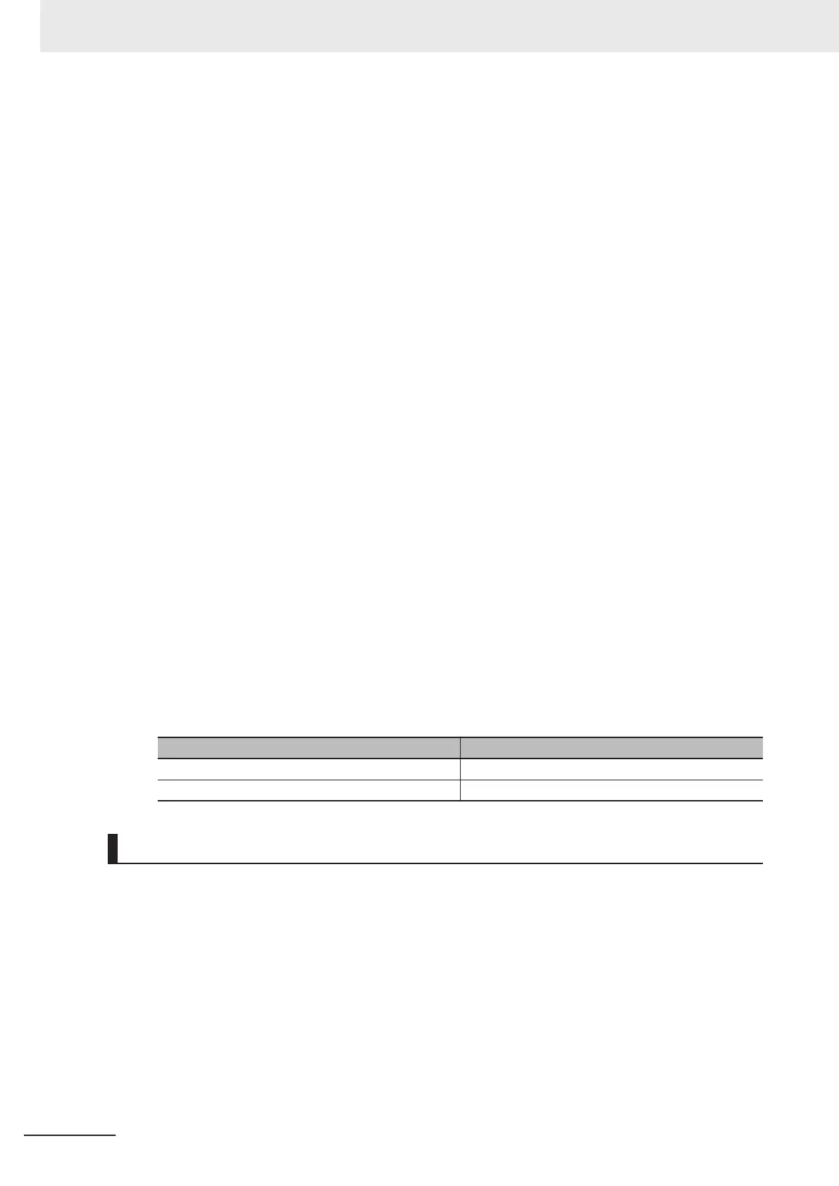
In addition, set a carrier frequency appropriate for the wiring distance between the inverter and
the motor according to the table below.
Capacity Wiring distance between inverter and motor
3.7 kW max. 50 m max.
5.5 kW min. 100 m max.
External Braking Resistor Connection Terminal (P(+), DB)
When driving a load with a large inertia or a vertical axis, regenerated energy is fed back to the inver-
ter when it is decelerating or generating downward movement.
If the amount of regenerative energy exceeds the amount allowable for the inverter, an overvoltage is
detected. Use braking resistors or regenerative braking units to prevent this.
Using built-in regenerative braking circuit
All models of the 3G3M1 Series Inverter have built-in regenerative braking circuit.
To improve the braking capacity, connect the optional external braking resistor to these terminals
(P(+), DB).
•
Wiring diagram
2 Design
2-50
M1 Series Standard Type User's Manual (I669)

 Loading...


