L1
L2
L3
L1/R
L2/S
L3/T
U
V
W
M
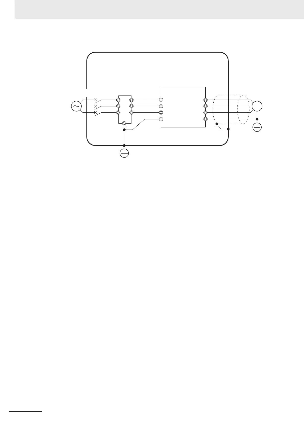
(Power supply)
Molded case
circuit breaker
*1
Inverter
Motor
EMC
noise filter
L1' (Red)
L2' (White)
L3' (Blue)
Control panel made of metal
Shielded wire
G
G G
E
Connection Example
Wiring between inverter and motor
For cables between the inverter and motor, be sure to use shield braided cables.
Keep the cables as short as possible.
Measures against noise for compliance with EMC Directive
• Keep the power cable of the inverter and the EMC noise filter wiring as short as possible.
Use a shield braided cable.
• For the shield braided cable, use a tinned copper shielded cable with a shield factor of 85%.
• Be sure to connect the ground cable separately from the shielded cable. Use the ground cable
as thick and short as possible to wire.
•
Use shield braided cables for connection between the inverter and the motor. Keep the cables as
short as possible at a length 20 m or less, with the cable shield grounded at each end. Installing
a clamp filter near the inverter output terminals is an effective countermeasure.
• Ground the motor frame, the shield of the motor cable, and the terminal housing adequately.
The motor terminal housing may not contact with the chassis due to the rubber bushing or the
screw hole for motor ground terminal may be coated.
Check the contact performance. If there is any problem, take measures to enhance contact per-
formance.
• Use shielded cables for wiring to the control circuit terminal blocks and communications lines and
ground the shield of each cable on the inverter side. Grounding the cables at each end may in-
crease the effect.
• Connect the cable shield directly to a ground plate with a conductive cable clamp. At this time,
keep the shield strip length as short as possible.
• Make the contact area between the EMC noise filter/inverter and the ground plate as large as
possible to enhance contact performance. At this time, remove the paint etc. from the ground
plate.
• For the metal control panel door, use a conductive gasket to improve the shielding effect.
• In the same control panel, do not install equipment that generates non-EMC-compliant electro-
magnetic waves.
• Avoid conductor loops that encompass large areas.
2 Design
2-62
M1 Series Standard Type User's Manual (I669)

 Loading...


