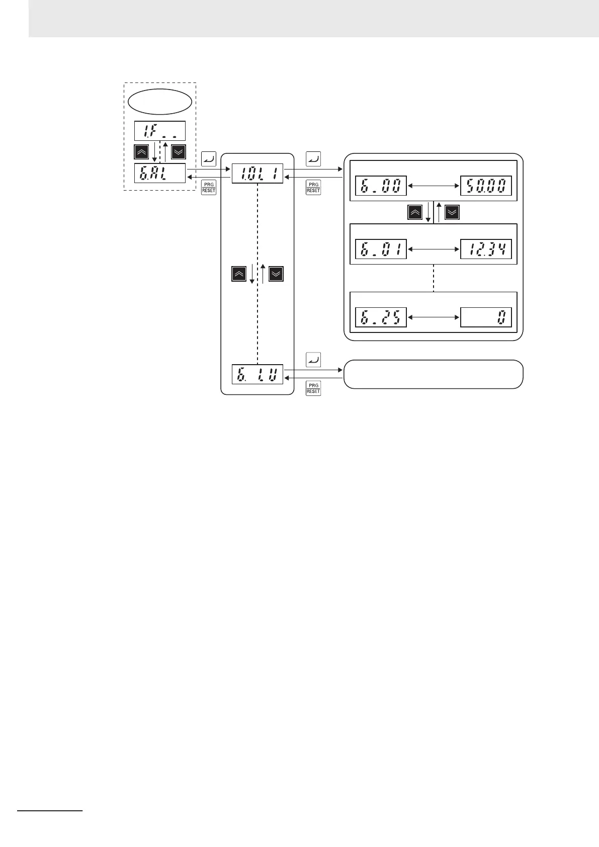
Program
Mode
Alarm list
Information on various operations
during alarm occurrence
Item No.
Output frequency
Switching in
approx.
one second
Item No. Output current
Switching in
approx.
one second
Item No.
Multiple sub code
Switching in
approx.
one second
Same as above
User preferences (user parameters)
Only parameters registered as user preferences at menu No. 0 “User preferences (user parame-
ters)” can be displayed, and the data of these parameters can be set.
To display parameters at menu No. 0 “User preferences (user parameters),” Operator Display Se-
lection (E52) must be set to “0: Parameter data setting mode (menu 0 and menu 1)” or “2: Full
menu mode.”
For details on registering user preferences (user parameters), refer to 7-7-6 User Parameter Set-
ting Function on page
7-80.
The following figure shows transition through “User preferences (user parameters).”
3 Operation and Test Run
3-12
M1 Series Standard Type User's Manual (I669)

 Loading...


