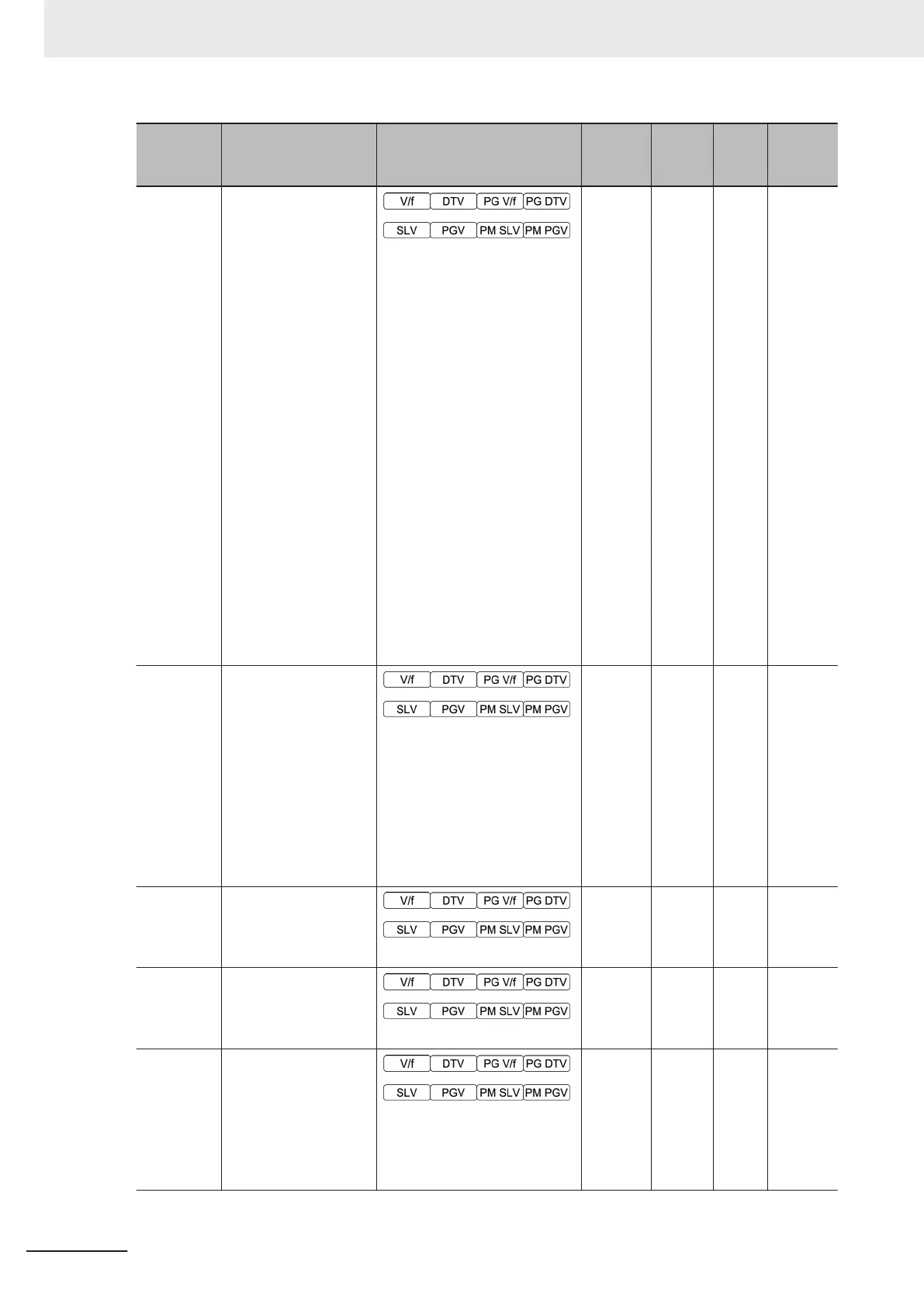
Parameter
No.
Function name Monitor or Data Range
Default
data
Setting
during
RUN
Unit Page
F01
1st Frequency Refer-
ence Selection
0 to 15
0: Operator (UP and DOWN
keys)
1: Analog voltage input (termi-
nal AI1)
2: Analog current input (termi-
nal AI2 (AII))
3: Analog voltage input (termi-
nal AI1) + analog current input
(terminal AI2 (AII))
5: Analog voltage input (termi-
nal AI2 (AIV))
7: UP/DOWN control
8: Digital Operator (UP and
DOWN keys)(balanceless-
bumpless switching available)
10: Pattern operation
12: Pulse train input
13: Calculation result
14: RS-485 communication
15: Fieldbus (Reserved)
0 - -
page
5-27
F02
1st RUN Command
Selection
0: Operator (Direction of rota-
tion input: terminal block)
1: External signal (Digital in-
put)
2: Operator (Forward rotation)
3: Operator (Reverse rotation)
4: RS-485 communication
5: Fieldbus (Reserved)
2 - -
page
5-25
F03
1st Maximum Output
Frequency
5.0 to 590.0 Hz
60.0 - Hz
page
5-19
F04 1st Base Frequency
5.0 to 590.0 Hz
50.0 - Hz
page
5-19
F05
1st Rated Voltage at
Base Frequency
80 to 240 V: AVR operation
(200 V class series)
160 to 500 V: AVR operation
(400 V class series)
200 - V
page
5-19
4 Parameter List
4-78
M1 Series Standard Type User's Manual (I669)

 Loading...


