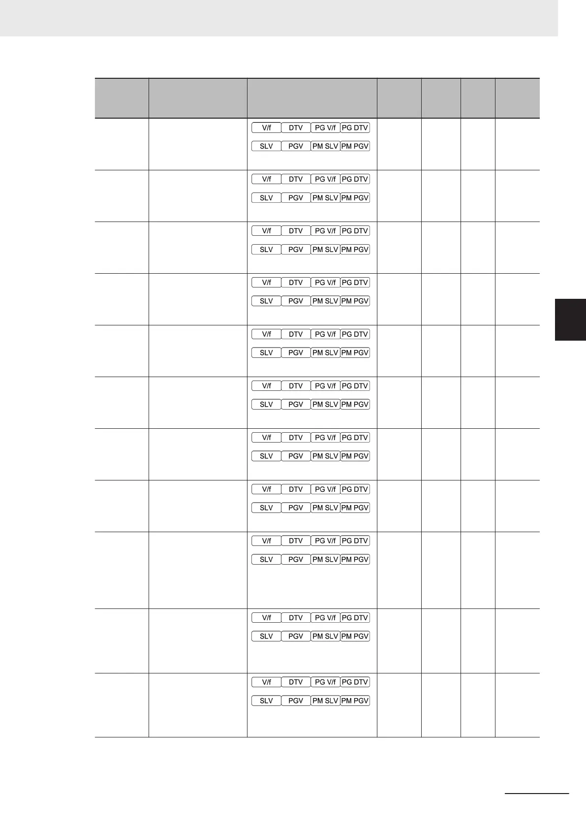
Parameter
No.
Function name Monitor or Data Range
Default
data
Setting
during
RUN
Unit Page
H388
Modbus Mapping 3 In-
ternal Register
0000 to FFFF Hex
0000
hex
- -
page
8-23
H389
Modbus Mapping 4 In-
ternal Register
0000 to FFFF Hex
0000
hex
- -
page
8-23
H390
Modbus Mapping 5 In-
ternal Register
0000 to FFFF Hex
0000
hex
- -
page
8-23
H391
Modbus Mapping 6 In-
ternal Register
0000 to FFFF Hex
0000
hex
- -
page
8-23
H392
Modbus Mapping 7 In-
ternal Register
0000 to FFFF Hex
0000
hex
- -
page
8-23
H393
Modbus Mapping 8 In-
ternal Register
0000 to FFFF Hex
0000
hex
- -
page
8-23
H394
Modbus Mapping 9 In-
ternal Register
0000 to FFFF Hex
0000
hex
- -
page
8-23
H395
Modbus Mapping 10
Internal Register
0000 to FFFF Hex
0000
hex
- -
page
8-23
H396
Modbus Mapping En-
dian Selection
0: Big endian
1: Little endian
2: Special endian
0 - -
page
8-23
H411
Input Phase Loss Pro-
tection Function Se-
lection
0: Disable (Continue to run)
1: Enable (Trip)
1
Availa-
ble
-
page
7-111
H412
Output Phase Loss
Protection Function
Selection
0: Disable (Continue to run)
1: Enable (Trip)
0
Availa-
ble
-
page
7-111
4 Parameter List
4-133
M1 Series Standard Type User's Manual (I669)
4-2 List of Parameters by Group
4
4-2-5 Parameter H (High Level Functions)

 Loading...


