HHD
F80 = 0
HND
F80=1
HD
F80=3
ND
F80=4
Three-phase 200 V full capacity OK OK - -
Three-phase 400 V full capacity OK OK OK OK
Single-phase 200 V (2.2 k or less) OK OK - -
Single-phase 200 V (3.7 kW) OK - - -
• For loads (such as fans and pumps) that do not require frequent use of the inverter above the rated
torque, the light load mode can be selected. The rated current of the inverter increases above that of
the heavy load mode, which enables the inverter to drive a motor one size larger. For details on rat-
ed current specifications, refer to 1-3-1 Standard Specifications on page 1-1
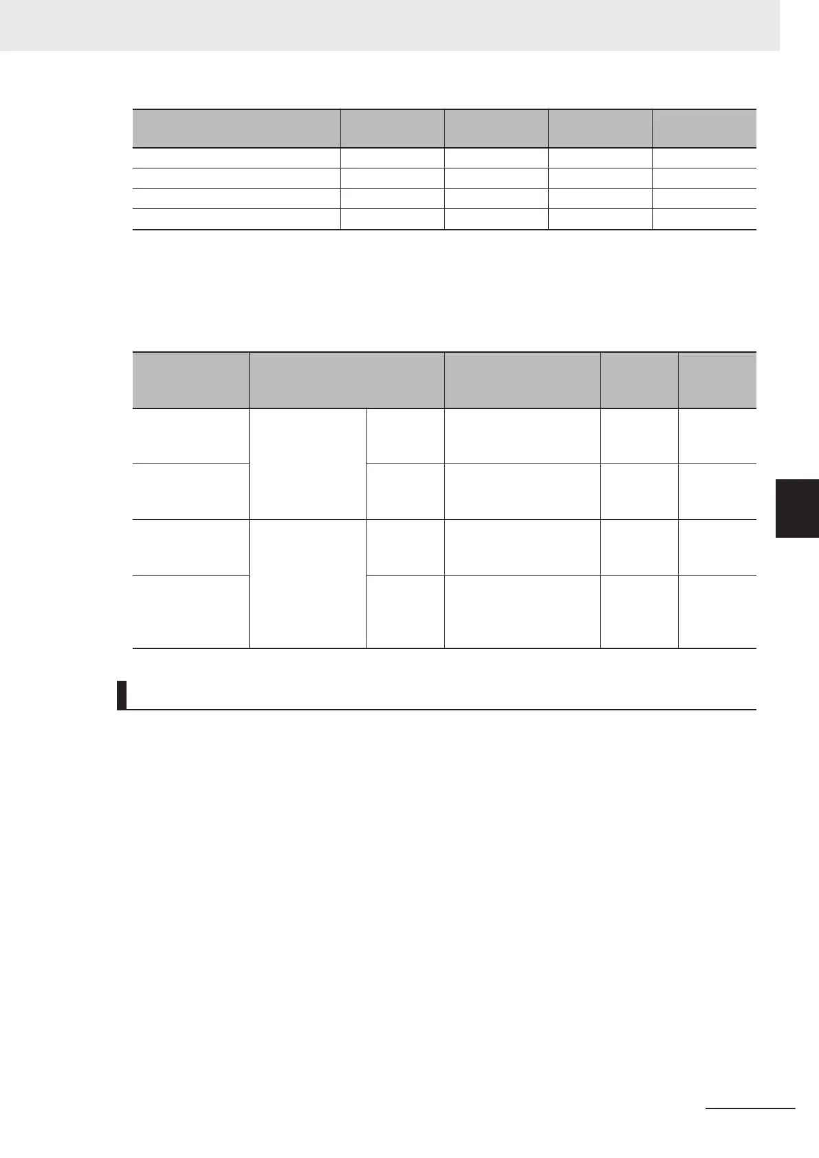
1. The overload capacity
differs as shown in the following table on each specification type.
F80 data Specification type
Continuous rated cur-
rent level
Ambient
tempera-
ture
Overload
capacity
0
Heavy load mode
HHD
Motor of same capacity
as inverter capacity can
be driven
Up to 50°C
150% 1 min
200% 0.5 s
3
(only for 400 V)
HD
Motor of capacity one size
larger than the inverter
capacity can be driven
Up to 40°C 150% 1 min
1
Light load mode
HND
Motor of capacity one size
larger than the inverter
capacity can be driven
Up to 50°C 120% 1 min
4
(only for 400 V)
HD
Motor of capacity one to
two sizes larger than the
inverter capacity can be
driven
Up to 40°C 120% 1 min
Related Parameters
• Some parameters are restricted by changing the setting of Load Mode Selection (F80).
When Drive Control Selection (F42/A14) = 0 to 6 (induction motor)
• The set values of the following parameters are overwritten with the following values according to
the new settings after changing Load Mode Selection (F80).
• Manual Torque Boost V
oltage (F09/A05), Overload Protect Level (F44/E147)
• The upper limit values of the following parameters change according to the new settings after
changing Load Mode Selection (F80). When the set values exceed the upper limit, they are over-
written with the upper limit.
• Carrier Frequency (F26), DC Injection Braking Level (F21/A10)
5 Basic Settings
5-13
M1 Series Standard Type User's Manual (I669)
5-2 Setting V/f Control
5
5-2-2 Load Mode Selection

 Loading...


