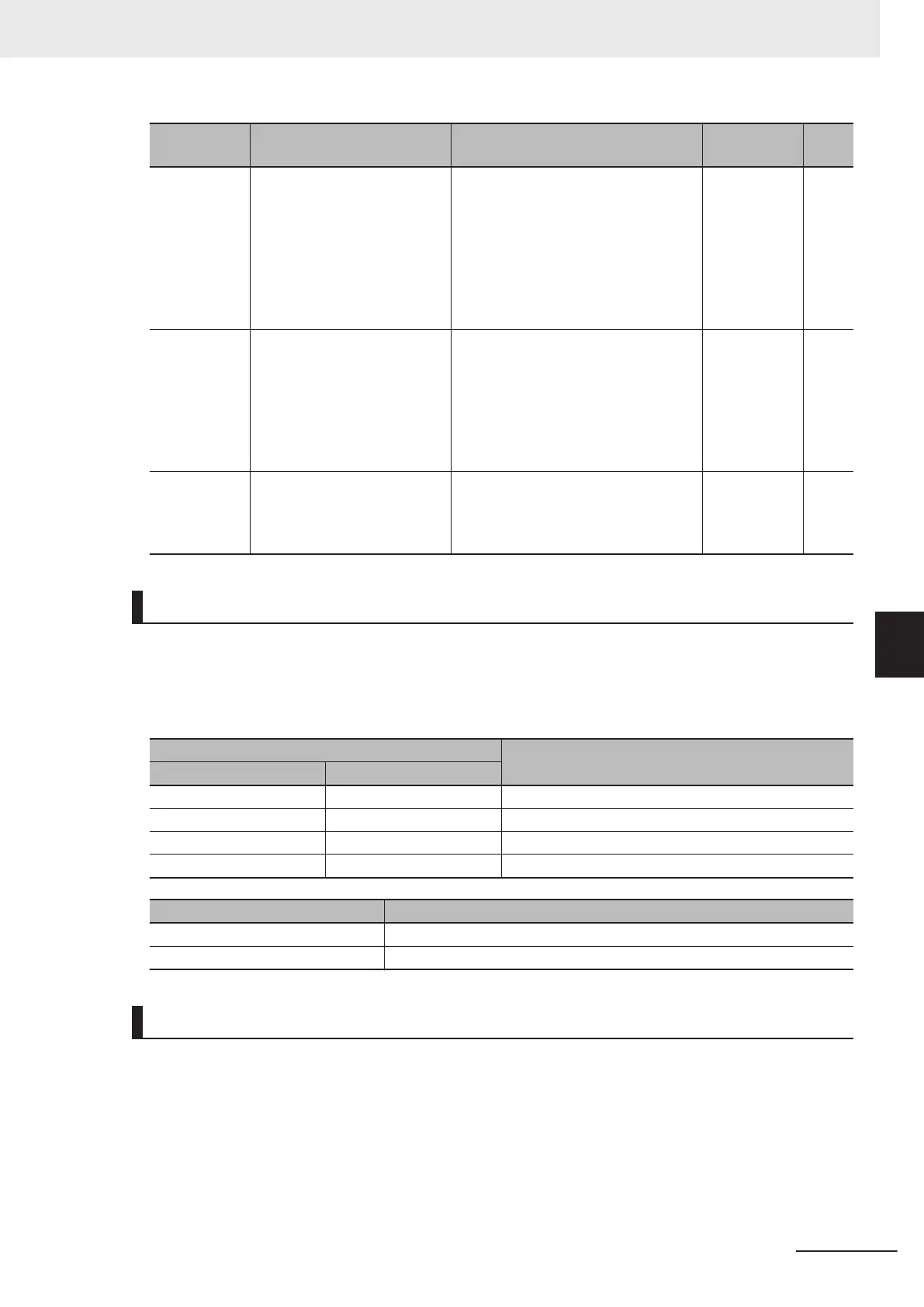
Parameter
No.
Function name Data Default data Unit
d07/A49/b49/r
49
Speed Control 1 Notch Filter
Resonance Frequency/Speed
Control 2 Notch Filter Reso-
nance Frequency/Speed Con-
trol 3 Notch Filter Resonance
Frequency/Speed Control 4
Notch Filter Resonance Fre-
quency
1 to 500 200 Hz
d08/A50/b50/r
50
Speed Control 1 Notch Filter
Attenuation Level/Speed Con-
trol 2 Notch Filter Attenuation
Level/Speed Control 3 Notch
Filter Attenuation Level/Speed
Control 4 Notch Filter Attenu-
ation Level
0 to 40 0 dB
E01 to E05,
E98, E99
Input Terminal [DI1] Function
Selection to Input T
erminal
[DI7] Function Selection
78: Speed control parameter selection
1
79: Speed control parameter selection
2
- -
Switching Speed Control Constants
In readiness for cases where speed control constants must be changed according to changes in load
or machine conditions, the 3G3M1 has four speed control constants. These can be switched by speed
control parameter selection 1 terminal input “MPRM1” and speed control parameter selection 2
“MPRM2.” Speed control constants 1 and 2 can also be switched by the “SET (2nd control)” terminal.
Input signal
Switching speed control constants
MPRM2 MPRM1
OFF OFF Speed control constant 1: d01 to d08
OFF ON Speed control constant 2: A43 to A50
ON OFF Speed control constant 3: b43 to b50
ON ON Speed control constant 4: r43 to r50
Input signal SET Switching speed control constants
OFF Speed control constant 1: d01 to d08
ON Speed control constant 2: A43 to A50
Speed Command Filter (d01/A43/b43/r43)
This parameter is for setting the time constant of the primary lag filter for the speed set value. Adjust
this parameter, for example, when overshooting in response to changes in the speed command is
large.
Setting a large filter time constant stabilizes the output and reduces overshoot in response to changes
in the speed setting though the speed response becomes slower.
6 Vector Control and Applied Functions
6-27
M1 Series Standard Type User's Manual (I669)
6-5 Speed Control
6
6-5-1 Speed Control Settings
 Loading...


