However, changes also in known command amounts are corrected after they appear in deviation
(speed command - actual speed value) later on. As the control value (torque command) is required in
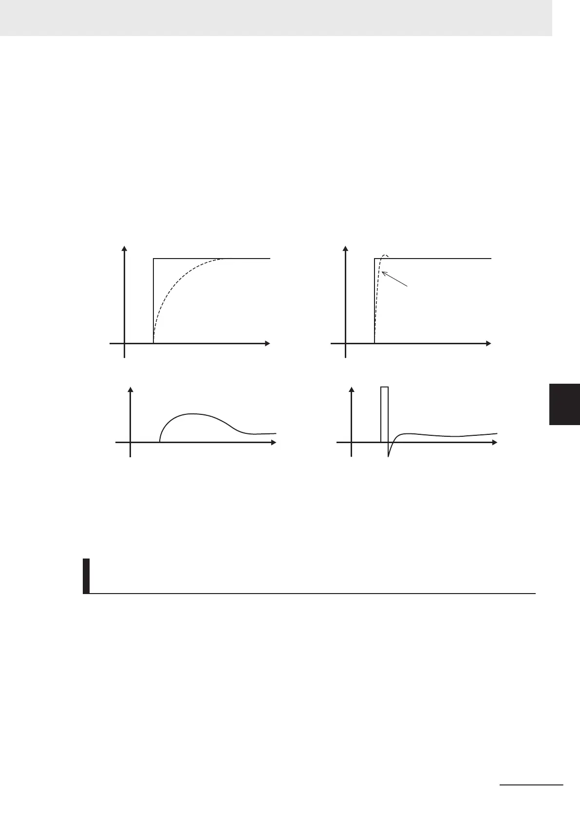
advance for known causes, faster-response control can be expected by adding that control value di-
rectly to the torque command. This parameter is for performing this kind of control. Feedforward con-
trol adds the torque that is determined from the amount of change in the speed command directly to
the torque command.
This is effective when the load inertia is already known. As shown conceptually in the figure below, the
speed of the actual value following the command amount when feedforward control is disabled and
when it is enabled is completely different. Note, however
, that, in order to obtain maximum effect, the
PI constants of feedback control should be adjusted to balance well with this set value.
Time
Sp
eed
0
Speed command value
Actual speed value
Time
Sp
eed
0
Speed command value
Actual speed value
Time
T
orque output
0
Torque command
Time
Torque output
0
Torque command
Although the above effect can be obtained by setting the P gain of the speed controller to a higher
value, increasing gain is counterproductive as is it also increases system response and produces ma-
chine resonance and vibration sound.
Notch Filter Resonance Frequency (d07/A49/b49/r49) and Notch Fil-
ter Attenuation Level (d08/A50/b50/r50)
The speed loop gain at only near a preset resonance point can be lowered to suppress machine reso-
nance. The notch filter can be used only when “vector control with speed sensor” is selected. Setting a
higher speed loop gain to increase speed response may result in machine resonance being generat-
ed.
To suppress machine resonance, the speed loop gain must be lowered to lower the overall speed re-
sponse. If the notch filter is used at this time, the speed loop gain at only near the preset resonance
point can be lowered, and the speed loop gain at other than the resonance point can be set higher. As
a result, the overall speed response can be increased.
When “0” (dB) is set to “attenuation level,” the notch filter is disabled.
6 Vector Control and Applied Functions
6-29
M1 Series Standard Type User's Manual (I669)
6-5 Speed Control
6
6-5-1 Speed Control Settings
 Loading...


