Item No.
Pa-
rame-
ter
No.
Item Range
Display contents (The value range de-
pends on the model)
4_18 W56
Pulse Input (Z Phase
[PIZ])
0 to 9999 [p/s]
1000 to 1600 [10p/s]
The pulse rate entered in the pulse input ter-
minal [PIZ] is displayed.
If the monitor value is 10000 or above, the
x10 LED lights up and the value of “monitor
value/10" is displayed.
4_24 X90 Reserved - -
4_36 X97
Input Input Terminal
[PTC] Input V
oltage
-12.0 to 12.0 [V]
The thermistor input terminal [PTC] input
voltage is displayed in increments of 0.1 V.
*Since this item is shared with other terminal
functions, “999” is displayed when it is disa-
bled due to switching by the hardware SW.
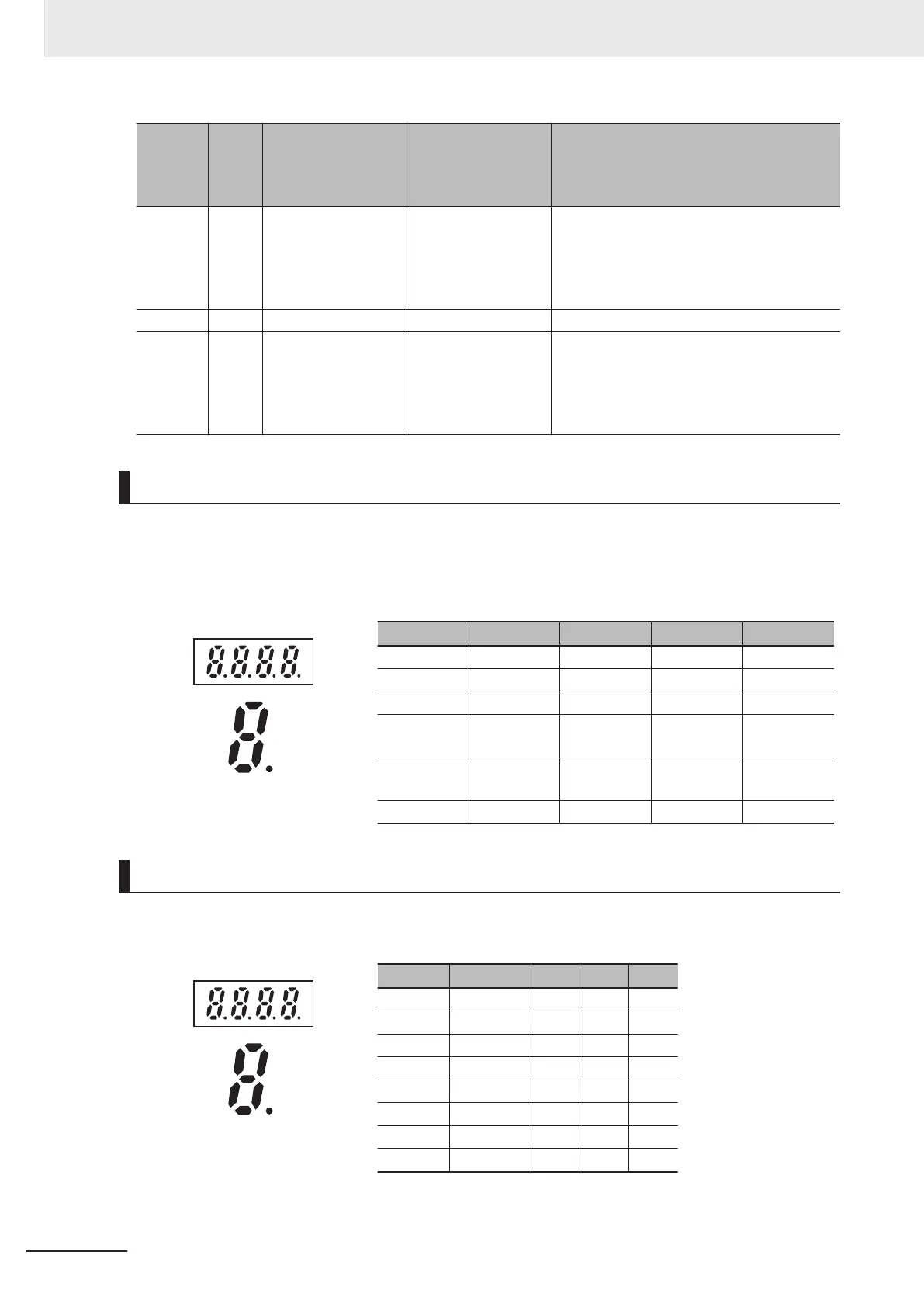
Digital Input/Output Terminal Monitor [4_00]
This function displays the ON/OFF status of the input/output signal of the digital input/output terminal.
The monitor displays the input/output status of the terminals depending on whether each segment of
the LED is ON or OFF.
The allocation of each segment and the input/output signal is described in the table below.
Segment LED4 LED3 LED2 LED1
a ROA, ROB DO1 - DI6
b - DO2 - DI7
c - - - DI1
d - -
EN1 ([SF1]
terminal)
DI2
e - -
EN2 ([SF2]
terminal)
DI3
f - - - DI4
LED4 LED3 LED2 LED1
a
b
c
dp
d
e
f
g
Communications Control Signal (Input/Output) Monitor [4_01]
The ON/OFF status of the digital input/output terminal instructed via communication based on RS-485
is displayed.
Segment LED4 LED3 LED2 LED1
a ROA, ROB DO1 - FW
b - DO2 - RV
c - - - DI1
d - - - DI2
e - - - DI3
f - - DI6 DI4
g - - DI7 DI5
dp - - RST -
LED4 LED3 LED2 LED1
a
b
c
dp
d
e
f
g
7 Other Functions
7-12
M1 Series Standard Type User's Manual (I669)

 Loading...


