Deceleration Setting During Current Limit for Restart Mode after
Power Interruption (H14)
During restart after a momentary power failure, if the output frequency of the inverter and the rotation
speed of the motor are not in sync, an overcurrent flows and current limitation is activated. If a current
limitation is detected, the output frequency is automatically lowered to be in sync with the motor rota-
tion speed. At Deceleration Setting During Current Limit for Restart Mode after Power Interruption
(H14), set the gradient (frequency fall rate (Hz/s)) for lowering the output frequency.
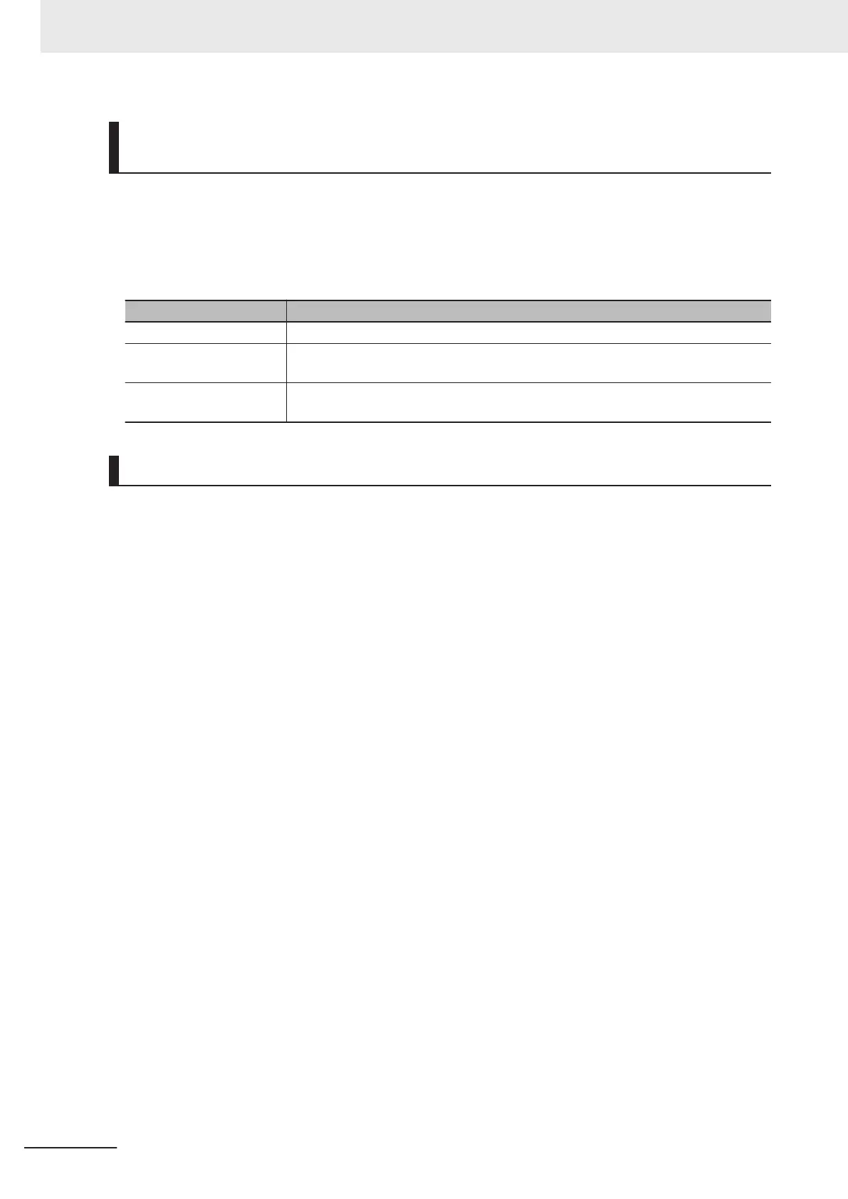
H14 data Output frequency lowering operation
0.00 Falls at the selected deceleration time.
0.01 to 100.00 Hz/s
Falls at the fall rate set at Deceleration Setting During Current Limit for Restart
Mode after Power Interruption (H14).
999
Falls in accordance with the PI controller of the current limitation process (the PI
constant is a fixed value inside the inverter).
Continuous Running Voltage Level (H15)
• Deceleration stop during momentary power failure
If “T
rip after decelerate-to-stop (Power Interruption Restart Mode Selection (F14) = 2)” or “Deceler-
ate-to-stop(w/o trip) (Deceleration Setting During Current Limit for Restart Mode after Power Inter-
ruption (F14) = 6)” is selected at the Power Interruption Restart (mode selection), then at the mo-
ment a momentary power failure occurs while the inverter is operating and the Main Circuit DC Volt-
age of the inverter falls below the continuous running level, the deceleration stop control is started.
Adjust the Main Circuit DC V
oltage level at which to start the deceleration stop control at Continuous
Running V
oltage Level (H15). During deceleration stop control, deceleration is performed while con-
trolling the Main Circuit DC Voltage at a constant level with a PI controller. The P (Proportional) and I
(Integral) of the PI controller are adjusted by Continuous Running at the Momentary Power Failure P
Proportional Gain (H92) and Continuous Running at the Momentary Power Failure Integral Time
(H93), respectively.
• Continuous running
If “Continue to run (Power Interruption Restart Mode Selection (F14) = 3)” is selected at the Power
Interruption Restart (mode selection), then at the moment a momentary power failure occurs while
the inverter is operating and the Main Circuit DC Voltage of the inverter falls below the continuous
running level, the operation continuation control is started.
Adjust the continuous running level at which to start the continuous running control at Continuous
Running Voltage Level (H15). During continuous running control, the operation is continued while
controlling the Main Circuit DC Voltage at a constant level with a PI controller.
7 Other Functions
7-56
M1 Series Standard Type User's Manual (I669)

 Loading...


