Overload Warning
The overload warning function causes the inverter to output an overload warning if the load is too
large, before it detects an overload trip.
• This is useful to prevent mechanical damage to transfer machines, etc. due to overweighed loading,
or stoppage of transfer lines due to an overload, through the use of the overload protection function
of the inverter.
•
To output this signal, allocate “38: OL (Overload warning)” or “37: OL2 (Overload warning 2)” to Out-
put Terminal [DO1] Function Selection (E20), Output Terminal [DO2] Function Selection (E21) and
Output Terminal [ROA, ROB] Function Selection (E27). (Two types of overload warning signals can
be output.)
• When using “38: OL (Overload warning),” set the overload warning detection level and overload
warning detection timer for each of 1st and 2nd control. When using “37: OL2 (Overload warning 2),”
set Overload early warning 2 Level (OL2) (E34) and Overload early warning 2 Detection Timer
(OL2) (E35) regardless of 1st and 2nd control.
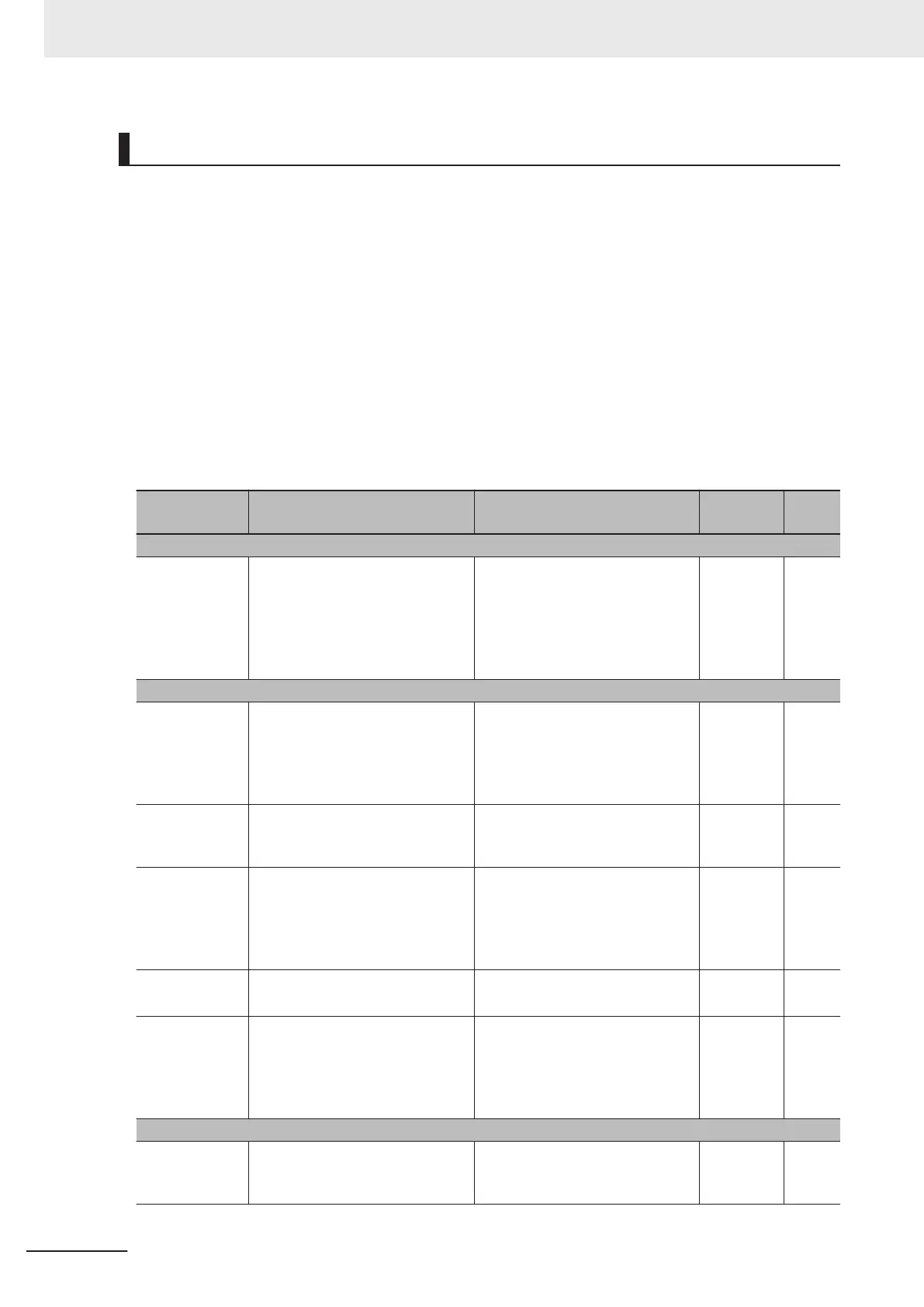
Parameter No. Function name Data
Default
data
Unit
Common setting for OL and OL2
E185
Overload Warning Detection Con-
dition Selection (OL1, OL2)
0 to 1
0: Output during acceleration/
deceleration and constant-speed
operation
1: Output only during constant-
speed operation
1 -
Overload warning OL (Set the detection level and detection timer for each of 1st and 2nd control)
E37
1st Overload Early Warning De-
tection Level
0.00; 0.01 to 3000
0.00: Disable
0.01 to 3000 A, setting range from
1% to 200% of the rated inverter
current.
21.00 A
E38
1st Overload Early Warning De-
tection T
imer / Low Current detec-
tion level (OL, LOC)
0.01 to 600.00 10.00 s
E55
2nd Overload W
arning Detection
Level
*1
0.00; 0.01 to 3000
0.00: Disable
0.01 to 3000 A, setting range from
1% to 200% of the rated inverter
current.
21.00 A
E56
2nd Overload Early Warning De-
tection T
imer
*1
0.01 to 600.00 10.00 s
E20, E21, E27
Output T
erminal [DO1] Function
Selection, Output Terminal [DO2]
Function Selection, Output Termi-
nal [ROA, ROB] Function Selec-
tion
38: OL (Overload warning) -
-
Overload warning OL2 (common to 1st and 2nd control)
E34
Overload early warning 2 Level
(OL2)
0.00; 0.01 to 3000
0.00: Disable
0.01 to 3000 A
21.00 A
7 Other Functions
7-84
M1 Series Standard Type User's Manual (I669)

 Loading...


