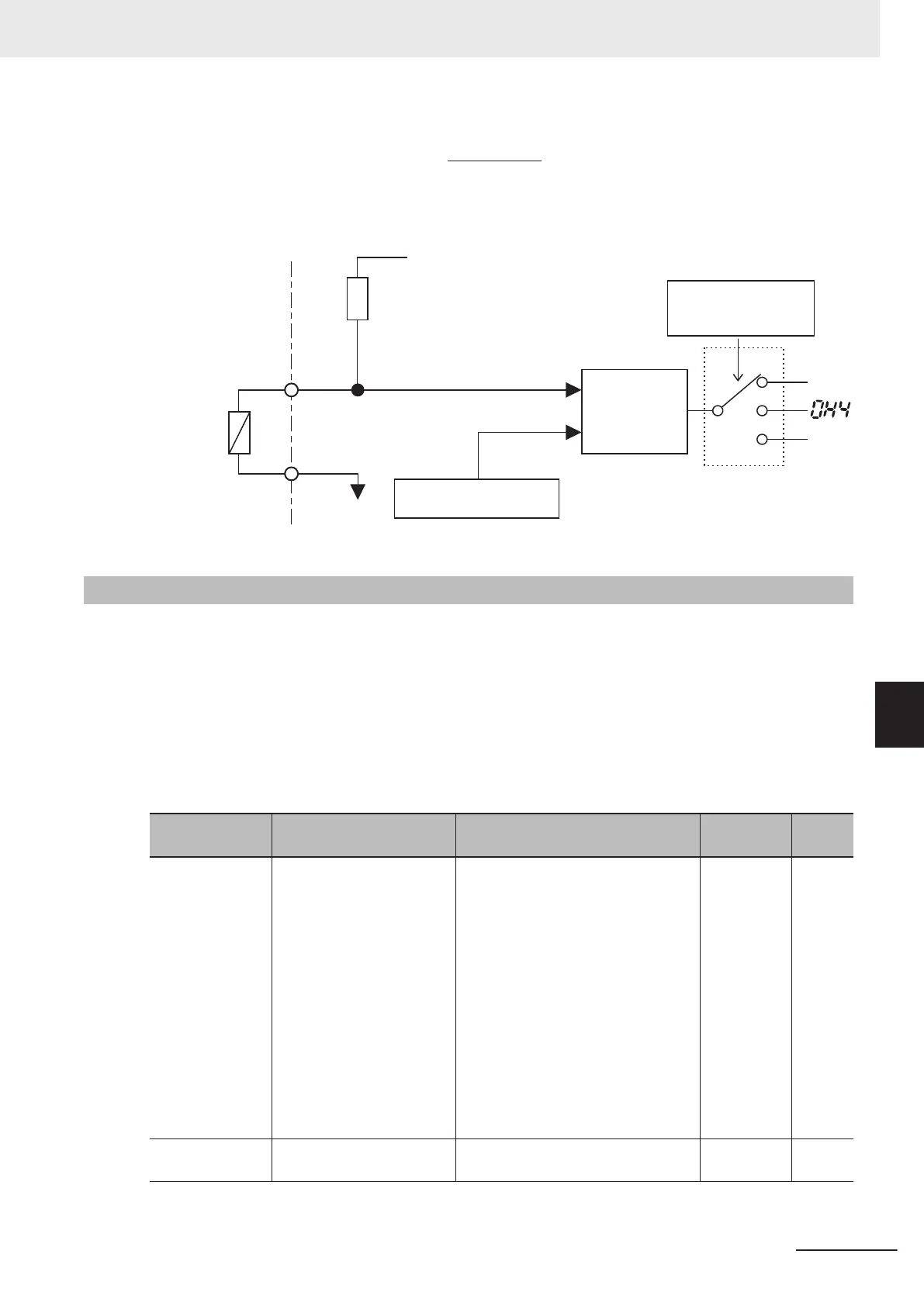
See below for the block part of the operation.
Thermistor Function
Selection (MOH)
H26
1st Thermistor Error
Detection Level (MOH) H27
Comparator
1 kΩ
Rp
V
P1
=10.5[V]
0[V]
PTC
thermistor
[PTC]
[AIC]
2
MOH
V
OH
1
0
7-8-6
Frequency Arrival Signal (FAR1 to 3, FDT1 to 4, FAR1FDT1)
The inverter outputs the frequency arrival signal when the output frequency reaches the set level.
Allocate “1: FAR1 (Frequency arrival signal 1 (constant speed)),” “2: FDT1 (Over set frequency arrival
signal 1),” “21: FAR2 (Frequency arrival signal 2),” “31: FDT2 (Over set frequency arrival signal 2),”
“72: F
AR3 (Frequency arrival signal 3),” “87: FAR1FDT1 (Frequency match detection),” “183: FDT3
(Set-frequency-only arrival signal),” or “185: FDT4 (Set-frequency-only arrival signal 2)” to Output Ter-
minal [DO1] Function Selection (E20), Output Terminal [DO2] Function Selection (E21) and Output
Terminal [ROA, ROB] Function Selection (E27).
Parameter No. Function name Data
Default da-
ta
Unit
E20, E21, E27
Output Terminal [DO1]
Function Selection, Output
Terminal [DO2] Function
Selection, Output Terminal
[ROA, ROB] Function Se-
lection
1: FAR1 (Frequency arrival signal 1
(constant speed))
2: FDT1 (Over set frequency arrival
signal 1)
21: FAR2 (Frequency arrival signal 2)
31: FDT2 (Over set frequency arrival
signal 2)
72: FAR3 (Frequency arrival signal 3)
87: FAR1FDT1 (Frequency match
detection)
183: FDT3 (Set-frequency-only arriv-
al signal)
185: FDT4 (Set-frequency-only arriv-
al signal 2)
-
E29
Frequency Arrival 2 ON
Timer (FAR2)
0.01 to 10.00 0.10
s
7 Other Functions
7-89
M1 Series Standard Type User's Manual (I669)
7-8 Functions Related to Protection, Warning and Various Output Signals
7
7-8-6 Frequency Arrival Signal (FAR1 to 3, FDT1 to 4, FAR1FDT1)

 Loading...


