Method of selecting light alarm causes
The causes of the light alarm that can be selected are allocated to 0 to 15 bits as shown below, and
are set and displayed in hexadecimals.
By setting the bit corresponding to the cause to be selected to 1, the concerned cause can be treat-
ed as a light alarm.
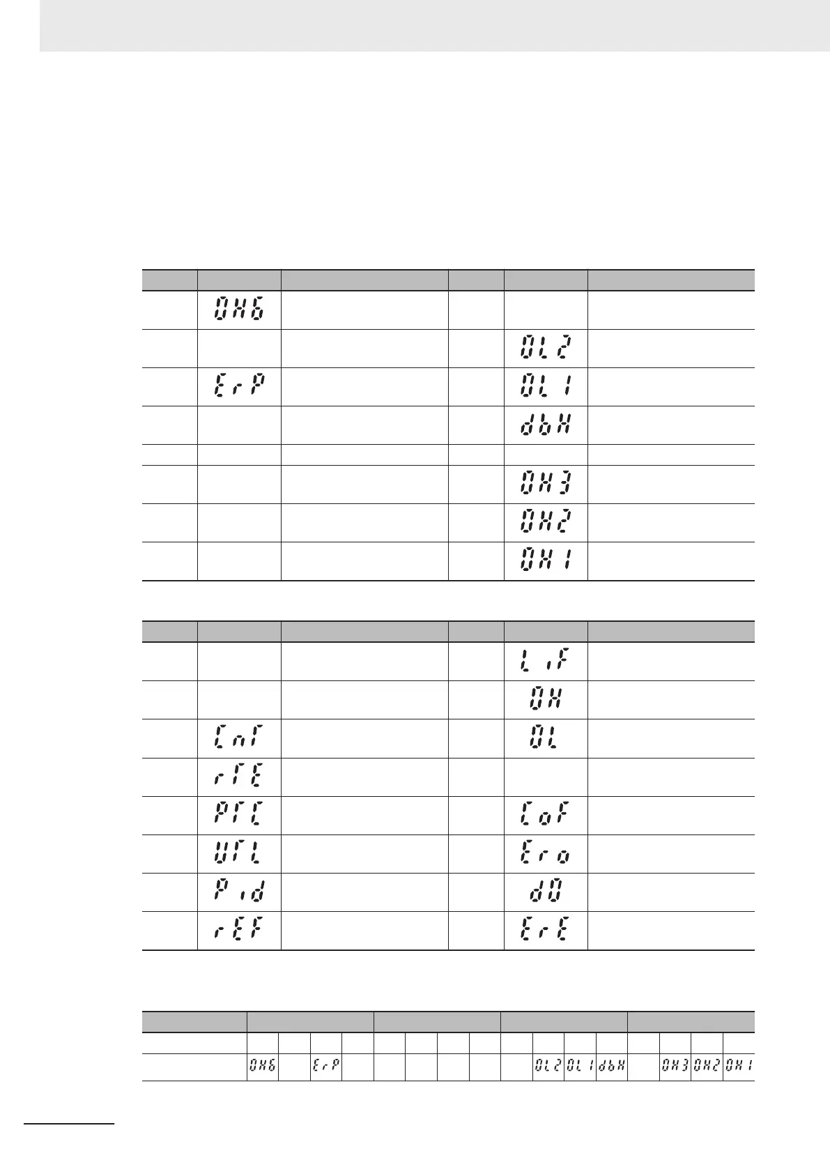
Light Alarm Selection 1 (H81)
Bit Symbol Description Bit Symbol Description
15
Inrush current prevention
resistor overheat
7 - -
14 - - 6
Motor 2 overload
13
RS-485 communications
error
5 Motor 1 overload
12 - - 4
Braking resistor overheat-
ing
11 - - 3 - -
10 - - 2
Inverter internal overheat-
ing
9 - - 1 External trip
8 - - 0 Cooling fin overheating
Light Alarm Selection 2 (H82)
Bit Symbol Description Bit Symbol Description
15 - - 7
Life warning
14 - - 6
Cooling fin overheating ear-
ly warning
13
Inverter life (Number of
startups)
5
Motor overload early warn-
ing
12
Inverter life (Cumulative run
time)
4 - -
11 Thermistor detection (PTC) 3
Current input disconnection
detection
10 Low torque detection 2 Positioning error
9
PID warning output 1
Excessive Positional Devia-
tion
8 Reference loss 0
Speed mismatch (Exces-
sive speed deviation)
(Example) When “RS-485 communications error,” “Motor 1 overload” or “Cooling fin overheating” is
selected at H81.
LED No. LED4 LED3 LED2 LED1
Bit 15 14 13 12 11 10 9 8 7 6 5 4 3 2 1 0
Symbol -
- - - - - - -
7 Other Functions
7-110
M1 Series Standard Type User's Manual (I669)

 Loading...


