Hold function : When the power is turned ON, the warning output turns OFF even within the warning
range. The warning output is enabled when it goes outside the warning range and then
again enters the warning range.
Touch probe
function
: Once the warning output turns ON after entering the warning range, the warning output
does not turn OFF even if it goes outside the range. To release the latch, either press the
key on the Operator, or turn ON the RS allocated to the multifunction input terminal.
• The OD terminal has an OFF delay of 0.1 s. The final OFF delay time becomes the time obtained by
adding 0.1 s to Output T
erminal [DO1] OFF Delay T
ime (H310), Output T
erminal [DO2] OFF Delay
Time (H312) and Output Terminal [ROA, ROB] OFF Delay Time (H314).
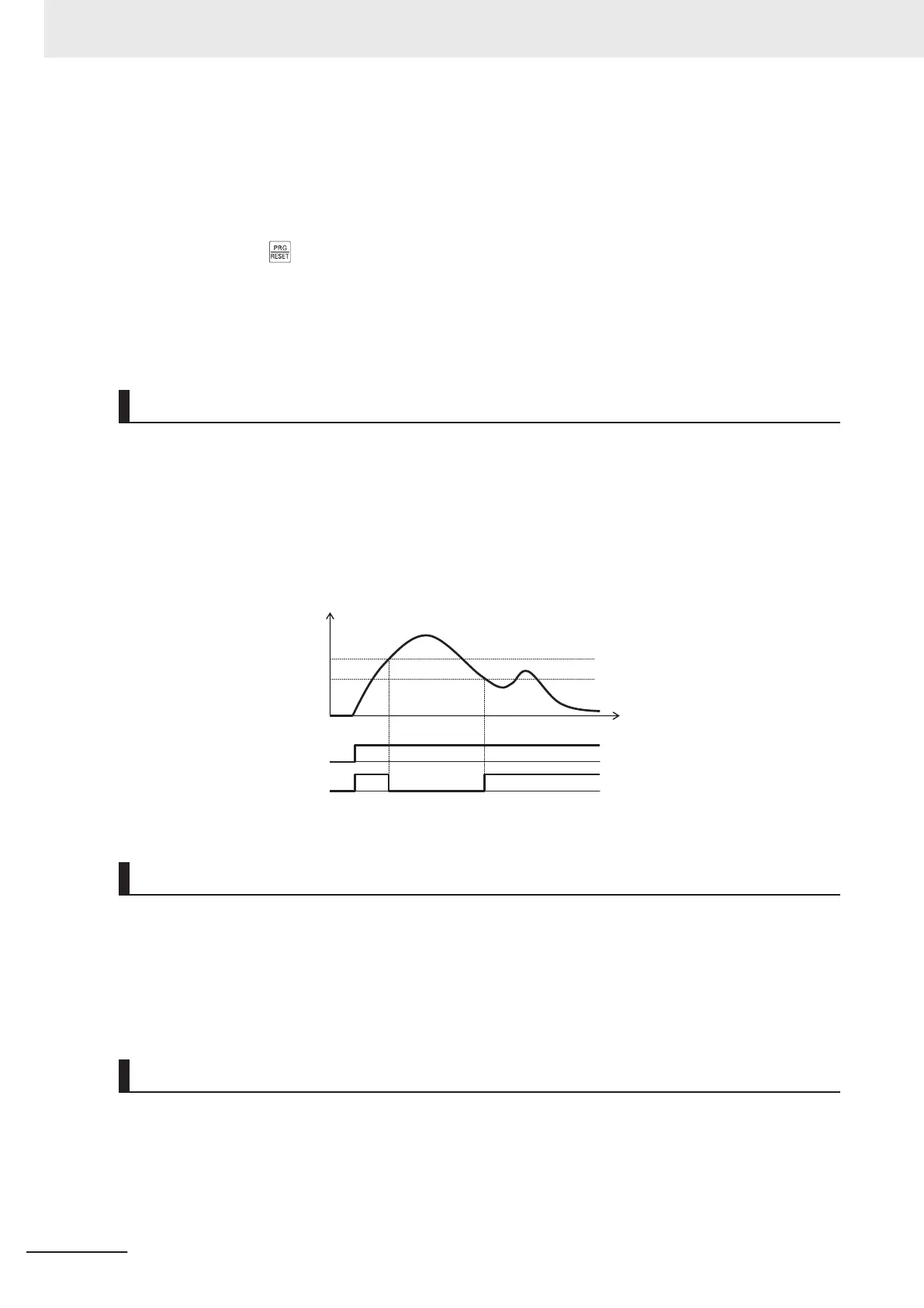
Feedback Comparison Signal
If PID feedback is outside the setting range, the signal is output to the multifunction output terminal.
T
o output this signal, allocate “186: FBV (PID FB status output)” to Output Terminal [DO1] Function
Selection (E20), Output T
erminal [DO2] Function Selection (E21) and Output T
erminal [ROA, ROB]
Function Selection (E27).
Set Feedback Value Comparison Signal Off Level (H438)/Feedback Value Comparison Signal On Lev-
el (H439) in units of percentage with 1st Maximum Output Frequency (F03)/2nd Maximum Output Fre-
quency (A01) as 100%.
ON
OF
F
OFF
ON
H438 Feedback Value
Comparison Signal Off Level
H439 Feedback Value
Comparison Signal On Level
Time
PID feedback value
FW input
FBV output
PID Feedback Value Monitor (Monitor Mode: 3_11)
The PID feedback value is converted to the control-target physical quantity (such as the temperature,
pressure, etc.) using the data of PID Control Maximum Scale (J106) and PID Control Minimum Scale
(J107).
Display value = (PID feedback value (%)/100) × (Maximum scale - Minimum scale) + Minimum scale
If PID control is disabled, “----” is displayed.
PID Integral Reset (PIDC)
Use this function to clear the integral value of PID operation.
To output this signal, allocate “33: PIDC (PID integral reset)” to Output Terminal [DO1] Function Selec-
tion (E20), Output Terminal [DO2] Function Selection (E21) and Output T
erminal [ROA, ROB] Function
Selection (E27).
The values are cleared each time the PIDC terminal is turned ON.
7 Other Functions
7-134
M1 Series Standard Type User's Manual (I669)
 Loading...


