EasyManuals Logo

Omron M1 Series User Manual

Omron M1 Series
808 pages
To Next Page IconTo Next Page
To Previous Page IconTo Previous Page
Page #654 background imageLoading...
Page #654 background image
8-2
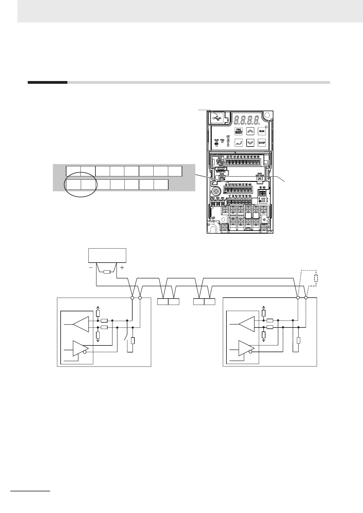
RS-485 Terminal Arrangement and
Connection
The communications terminals are arranged as follows.
+24DI7 DICDOC DI6DO2
AO
DO1
DIC +24PIB PIZPIA
SP
SN
Terminating resistor
selector switch (SW6)
RS-485 terminal
USB port is intended for computer only.
SP SN
SN
SP
SP SN
110
W
3G3M1 (No.2) 3G3M1 (No.3)
3G3M1 (No.1)
3G3M1 (No.n)
SN
SP
110
W
*1
External
equipment (Master)
*1. If the communications are unstable, install a terminating resistor appropriate to the impedance of the cable to
each cable end. The resistance of the terminating resistor built into this inverter is 110 Ω.
8 Communications Functions
8-4
M1 Series Standard Type User's Manual (I669)

Table of Contents

Questions and Answers:

Question and Answer IconNeed help?

Do you have a question about the Omron M1 Series and is the answer not in the manual?

Omron M1 Series Specifications

General IconGeneral
Input Voltage200-240V AC
Output Voltage3-phase 200 to 240 VAC
Protection FunctionsOvercurrent, Overvoltage, Undervoltage, Overheating, Short Circuit
CommunicationRS-485, Modbus RTU
EnclosureIP20
Cooling MethodFan Cooled
Operating Temperature-10°C to +50°C
Humidity5-95% (non-condensing)
AltitudeUp to 1000m
Frequency Range0.5-400 Hz
Storage Temperature-20°C to +65°C

Related product manuals