Note
Because this inverter is designed to establish co-inverter communication as broadcast communications
(Station No. 0), communications data is sent to all stations. Therefore, slaves that are not specified as the
recipient on the master side receive the data once, but discard internally the data not addressed to them.
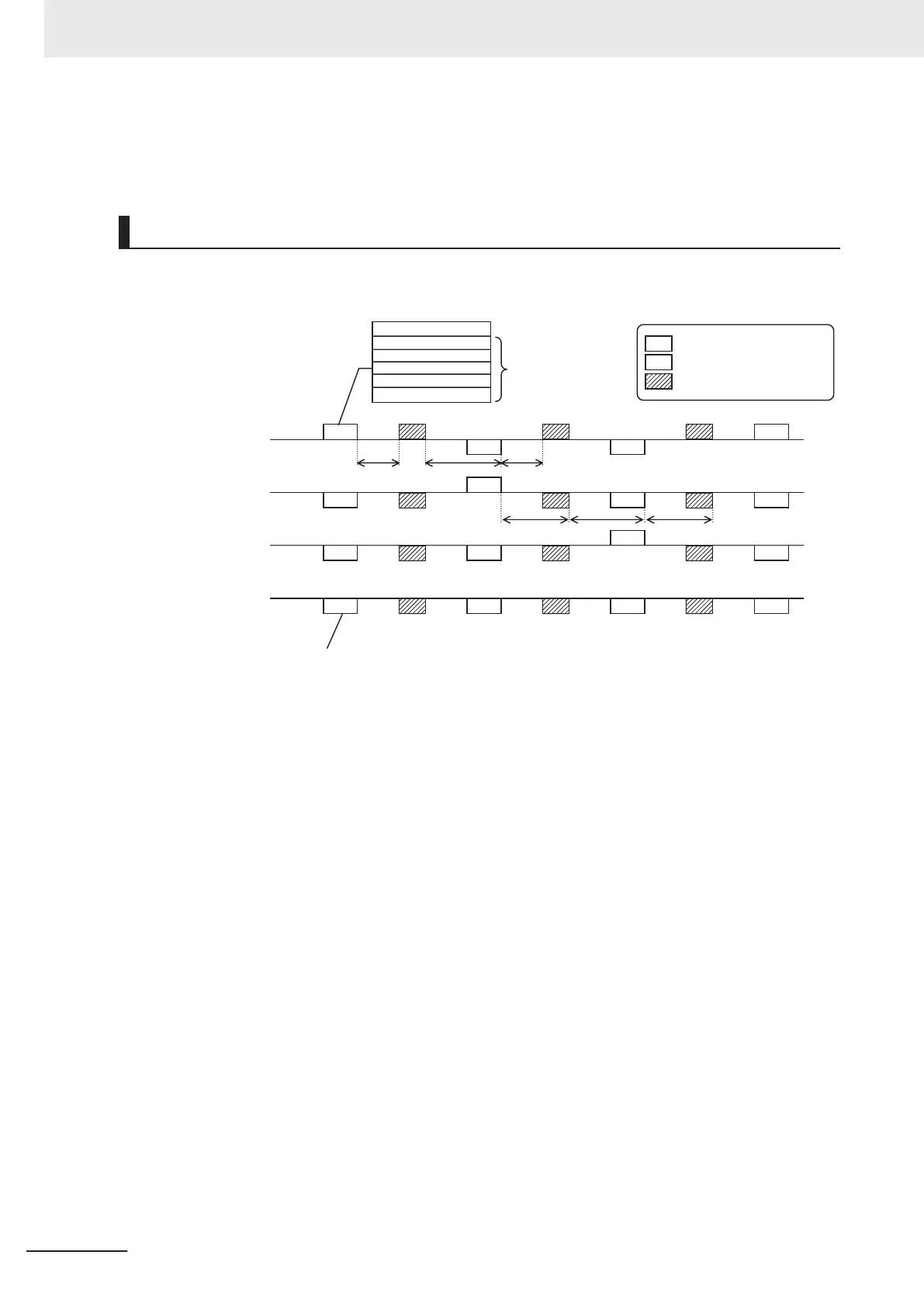
Example of Co-inverter Communication Sequence
The sequence diagram below shows co-inverter communication among four inverters with station
numbers from 1 to 4, where Stations No. 1 to 3 are set as the master inverter.
M
S
S
S
M
S
S
S
M
S
S
S
M
S
S
S
02 xxxx xxxx
02 xxxx xxxx
03 xxxx xxxx
03 xxxx xxxx
t3 t2
t3 t3
t1
M
S
t3
Station No. register data
Up to five recipients
can be specified.
Data sent from master
Data received by slave(s)
Master switching command
Inverter Station No. 1
Management
Inverter Station No. 2
Inverter Station No. 3
Inverter Station No. 4
Send
Receive
Send
Receive
Send
Receive
Send
Receive
All slaves receive data from the master
but discard it if not destined to them.
t1: Silent Interval + Communication Wait Time ({y19})
t2: Silent Interval + Communication Wait Time ({y19})
t3: Communication Error Timeout Time ({y18})
• Be sure to set the RS-485 Communication Timeout Time (y18) to other than 0.00 (one second or
longer is recommended) on the management inverter. When this parameter is set to 0.00, the inver-
ter's communications function will stop if no data is received from the master inverter. If it stops
working, cycle the power supply of the management inverter.
• The communications error timeout timer starts when the inverter starts waiting for data reception
and times out when it cannot complete data reception within the set time. If a timeout occurs, the
inverter performs the operation set in the Operation Selection on Communication Error (y12). (t3 in
above diagram)
• When the management inverter is the master, the master switching command will be sent with a
wait time of silent interval + RS-485 Communication Response Interval Time (y19) after the master
inverter sends data. (t1 in above diagram)
• When an inverter other than the management inverter is the master, the master switching command
will be sent with a wait time of silent interval + RS-485 Communication Response Interval Time
(y19) after receipt of data sent from the master inverter. (t2 in above diagram)
• When the Co-inverter Communication Start Selection is set to “1: Constant communication,” the
management inverter starts sending data as soon as the power supply is turned on. Therefore, if the
power-on timing of any other inverter is delayed, the communications cannot be established normal-
ly, which results in a communications timeout error on the management inverter. When set to con-
stant communication, check that the startup of other inverters is completed and power on the man-
agement inverter finally.
8 Communications Functions
8-32
M1 Series Standard Type User's Manual (I669)
 Loading...


