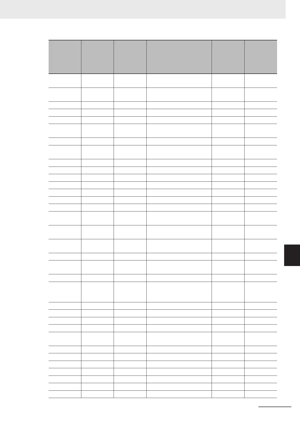
Parameter
No.
MODBUS ad-
dress (MSB)
MODBUS ad-
dress (LSB)
Parameter name
Communica-
tion data for-
mat (during
single-word
access)
Communica-
tion data for-
mat (during
double-word
access)
M59 5100h -
Motor Electronic Thermal
Monitor
1 -
M61 5102h -
Inverter Internal Air Tempera-
ture Monitor
4 -
M62 1018h - Fin Temperature Monitor 4 -
M63 5104h - Load Factor Monitor 6 -
M64 5105h - Motor Output Monitor 6 -
M65 5106h -
Motor Output Monitor on
Alarm
29 -
M66 5107h - Speed Detection Monitor 29 -
M67 5108h -
Transmission Error Transac-
tion Code for RS485 Port
20 -
M68 5109h - Reserved 29 -
M69 510Ah - Inverter Rated Current 19 -
M70 510Bh - Running Status 3 Monitor 44 -
M71 510Ch - Input Terminal Monitor 14 -
M72 510Dh - Reserved 29 -
M73 510Eh - PID Output Monitor 29 -
M74 510Fh - Running Status 2 Monitor 76 -
M76 5111h -
Service Life of Main Circuit
Capacitor Elapsed T
ime
74 -
M77 51
12h -
Service Life of Main Circuit
Capacitor Remaining Time
74 -
M78 51
13h -
Rotation Speed Command
Monitor
2 -
M79 5114h 5115h Rotation Speed Monitor 2 2
M81 5117h -
1st Remaining Time before
the Next Motor Maintenance
74 -
M84 100Ch - Torque Command at Final 2 -
M85 511Bh -
1st Remaining Startup Times
before the Next Motor Mainte-
nance
1 -
M86 511Ch - Latest Light Alarm Factor 41 -
M87 511Dh - Light Alarm Factor Last 41 -
M88 511Eh - Light Alarm Factor 2nd Last 41 -
M89 511Fh - Light Alarm Factor 3rd Last 41 -
M95 5125h 5126h
Cumulative Running Time at
T
ripping
1 1
M96 0039h -
Fourth Last Alarm Contents 10 -
M97 0043h - Fifth Last Alarm Contents 10 -
M98 5129h - Warning status monitor 1 -
M114 519Bh 519Ch Reserved 12 6
M115 519Dh - PID Output Non Filter 4 -
W01 1003h - Running Status 1 Monitor 16 -
W02 5242h 5243h Frequency Reference Monitor 22 5
8 Communications Functions
8-77
M1 Series Standard Type User's Manual (I669)
8-9 Modbus Communication Data Lists
8
8-9-2 Register List
 Loading...


