Alarm
code
Alarm
sub-
code
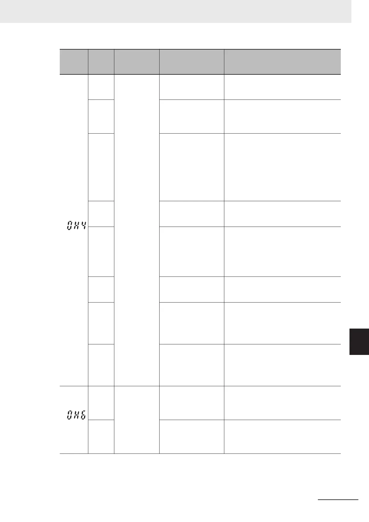
Name Description Check point and remedy reference
(0H4)
Motor protec-
tion (PTC ther-
mistor)
(1) The motor ambient
temperature exceeds
the specification range
Measure the ambient temperature.
→ Reduce the ambient temperature.
(2) Motor cooling sys-
tem damaged
Check that the motor cooling system is oper-
ating correctly.
→ Replace or repair the motor cooling
system.
(3) High load Measure the output current.
→
Reduce the load (use the Overload ear-
ly warning 2 Level (OL2) (E34), and re-
duce the load before an overload oc-
curs.) (During winter
, the load may in-
crease.)
→
Reduce the ambient temperature.
→
Increase the Carrier Frequency (F26).
(4) Incorrect PTC ther-
mistor operating level
(H27*)
Check the PTC thermistor specifications,
and recalculate the detection voltage.
→ Change the parameter data.
(5) Inappropriate PTC
thermistor settings
Check the Thermistor Function Selection
(MOH) (H26*) and terminal AO function tog-
gle switch (SW5).
→ Change the thermistor that uses H26*
to suitable settings, and set SW5 to
PO.
(6) 1st Manual Torque
Boost V
oltage (F09*)
too high
Check F09* data, and readjust so that this
does not stall even if data is lowered.
→ Adjust F09*.
(7) Error in V/f settings
Check that 1st Base Frequency (F04*) and
1st Rated Voltage at Base Frequency (F05*)
match the rated nameplate value.
→ Match these to the rated nameplate val-
ue.
(8) Error in parameter
settings
While not using PTC thermistor
, the Thermis-
tor Function Selection (MOH) (H26*) is in an
operation state.
→ Change Thermistor Function Selection
(MOH) (H26*) to 0 (Disable).
(0H6)
Inrush current
prevention re-
sistor overheat
(1) The inverter power
supply has been turned
OFF and then ON fre-
quently
.
Reduce the frequency at which the power
supply is turned OFF and then ON.
→
T
urn OFF and then ON less than once
every 30 minutes.
(2) The inverter power
supply has not been
turned OFF and then
ON frequently.
An error is generated each time the power
supply is turned OFF and then ON.
→ The inrush current protection circuit is
damaged. Request repair.
9 Troubleshooting
9-19
M1 Series Standard Type User's Manual (I669)
9-1 Alarm Display and Remedies
9
9-1-2 Alarm Code List

 Loading...


