It automatically increases the deceleration time to prevent the occurrence of an overvoltage in
the main circuit.
• Set a longer deceleration time
Increase the deceleration time to prevent the occurrence of an overvoltage in the main circuit.
This decreases the amount of regenerative energy per unit time.
• Select free-run stop
This prevents the regenerative energy from being fed back to the inverter.
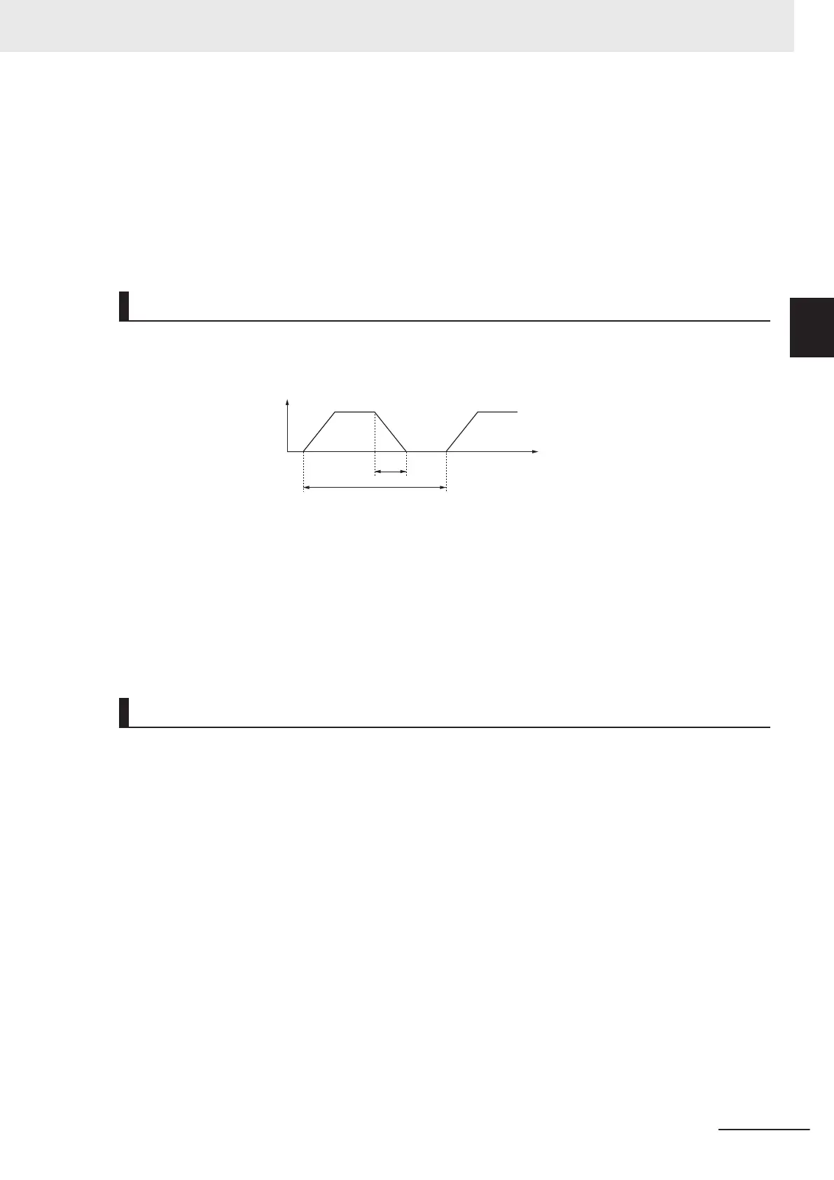
Simplified Braking Resistor Selection
This is a simple method to select an appropriate braking resistor based on the percentage of the time
in which regenerative energy is produced in a normal operation pattern.
Time
R
o
tation speed
[r/min]
t
N
T
Usage rate [%ED] = 100 × t / T
t : Deceleration time (regenerative time) [s]
T : 1cycle operation time [s]
All models of the 3G3M1 Series Inverter have built-in regenerative braking circuit.
Select a braking resistor based on the usage rate calculated from the operation pattern.
Connect a braking resistor suitable for your inverter according to the braking resistor list provided in
the inverter manual/catalog.
Detailed Braking Resistor Selection
When the usage rate of the braking resistor selected on the previous section exceeds 10% ED, or
when an extremely large braking torque is required, use the method below to calculate a regenerative
energy and make your selection.
Appendix
A-15
M1 Series Standard Type User's Manual (I669)
A-4 Overview of Inverter Selection
A
A-4-3 Overview of Braking Resistor Selection

 Loading...


