6-9
6 Programming
NJ-series CPU Unit Software User’s Manual (W501)
6-2 POUs (Program Organization Units)
6
6-2-5 Details on Function Blocks
]
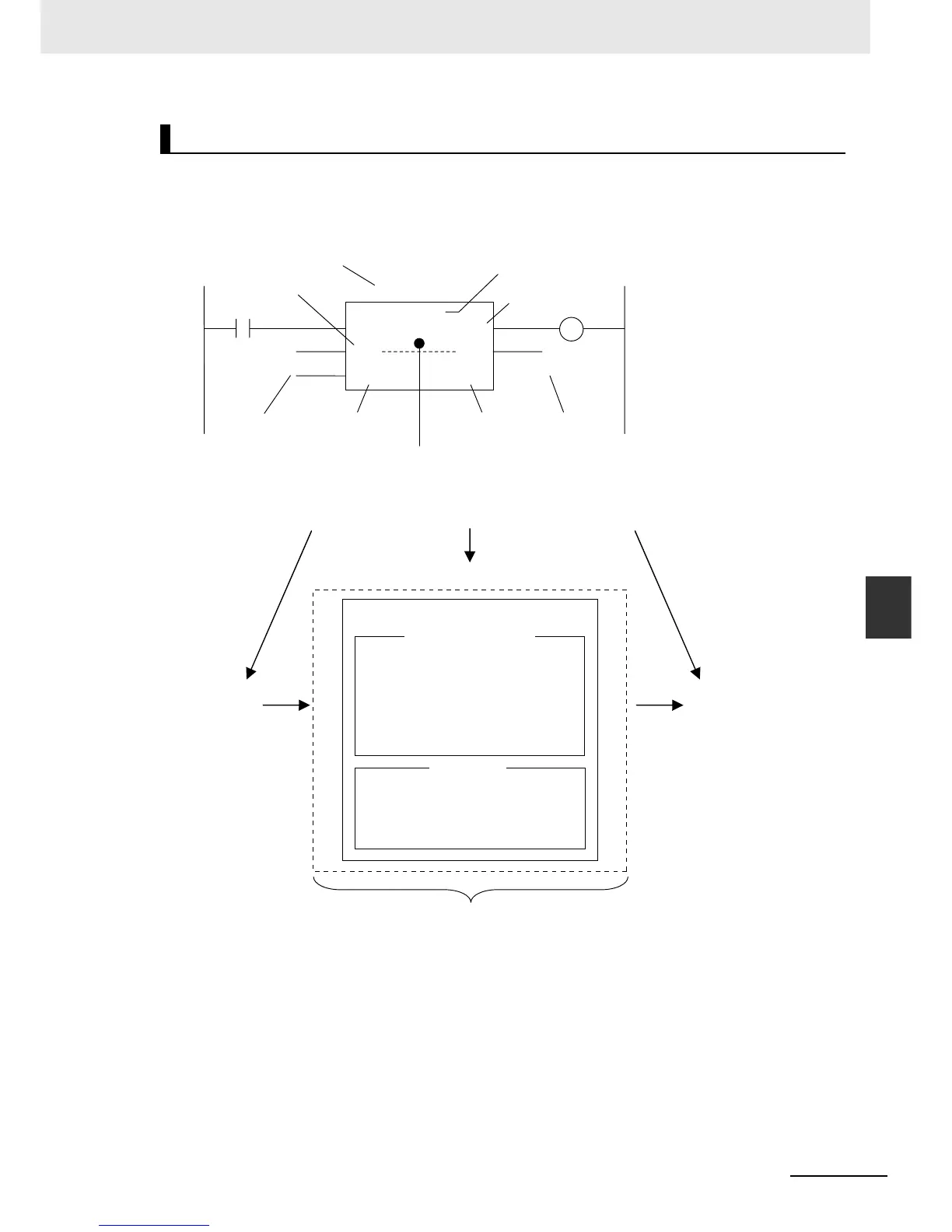
In a ladder diagram, function blocks are represented as rectangular boxes as shown below. Refer to
Calling Function Blocks from ST on page 6-10 for details about how to express function blocks in ST.
Function blocks consist of the following parts.
• Function Block in Ladder Diagram:
• Function Block Settings
When you create an instance of a function block definition, make the following settings.
Function Block Name or Instruction Name
This is the function block name or instruction name assigned in the function block definition when
the function block is created.
Instance Name
You give an instance name to a function block instance in a program to enable managing it. You
specify an instance name when you call a function block definition from a program or another func-
tion block.
Structure of Function Blocks
Function block name or instruction name
Input variable
Output variable
In-out variable
Input parameter
Output parameter
Algorithm
Instance name
Output variable
In
Q
MyFB
SetValue
InQ
InQ
SET
RESULT
Result
MyFB_instance
TRIG
OUT
Input parameters
Output parameters
Function block name
Instance name
Settings of a function block instance in a program
Internal variables
Input
variables
Output
variables
In-out
variables
Created in the Function Definition
Local Variable Table
Algorithm
•
Written as a ladder diagram or in ST.
• You can use any instructions,
user-defined functions, and user-
defined function blocks.

 Loading...


