6 Programming
6-72
NJ-series CPU Unit Software User’s Manual (W501)
6-5 Programming Languages
This section describes the programming languages in detail. Refer to the Sysmac Studio Version 1
Operation Manual (Cat. No. W504) for details on entering programs with the Sysmac Studio.
The languages used to express the algorithms in a POU (program, function, or function block) are
called the programming languages. There are two different programming languages that you can use
for an NJ-series Controller: ladder diagram language (LD) and ST (structured text) language.
The ladder diagram language (LD) is a graphical programming language that is written in a form that
appears similar to electrical circuits. Each object for processing, including functions and function blocks,
is represented as a diagram. Those objects are connected together with lines to build the algorithm.
Algorithms that are written in the ladder diagram language are called ladder diagrams.
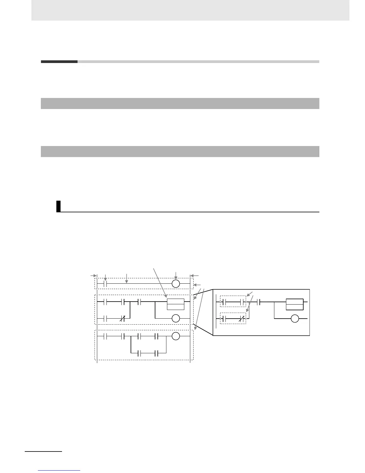
A ladder diagram consists of left and right bus bars, connecting lines, ladder diagram structure ele-
ments (e.g., inputs and outputs), functions, and function blocks.*
* Only Jump instructions and Label instructions are expressed with symbols that indicate the jumps and labels.
Algorithms are made of multiple rungs connected together. A rung is a connection of all configuration
elements between the left bus bar and the right bus bar. A program rung consists of logic blocks that
begin with an LD/LD NOT instruction that indicates a logical start.
Bus Bars
The vertical lines on the left and right sides of a ladder diagram are called the bus bars. These bus
bars always have a status of either TRUE or FALSE. If you think of the ladder diagram as an electri-
cal circuit, these states represent the flow of current through the circuit. When a POU that is written
as a ladder diagram is executed, the value of the left bus bar changes to TRUE. As a result, all
inputs and other configuration elements connected to the left bus bar also become TRUE. Execution
progresses as elements to the right are also changed to TRUE based on the operation of these con-
figuration elements. This cascade of the TRUE state is called the “power flow.” The left bus bar is the
source of this power flow.
6-5-1 Programming Languages
6-5-2 Ladder Diagram Language
General Structure of the Ladder Diagram Language
Output
Connecting line
Left bus bar
Right bus bar
Rungs
Logic blocks
Input
Function or function block

 Loading...


