6-73
6 Programming
NJ-series CPU Unit Software User’s Manual (W501)
6-5 Programming Languages
6
6-5-2 Ladder Diagram Language
Connecting line
The straight horizontal lines that connect the bus bar and the configuration elements are called con-
necting lines. Connecting lines can be either TRUE or FALSE and can transfer the power flow from
the left to the right.
Inputs
Inputs are placed along the connecting line to receive the power flow and operate accordingly. There
are several different types of inputs and, depending on their specifications, they will either transfer
the power flow from the left to the right or prevent the power flow from passing through. When an
input transfers the power flow to the right, the connecting line to the right of the input will become
TRUE. If the power flow is inhibited, the connecting line to the right of the input will remain FLASE.
For detailed specifications on inputs, refer to the NJ-series Instructions Reference Manual (Cat. No.
W502).
Output
Outputs are placed along the connecting line to receive the power flow and operate accordingly. An
output writes the TRUE or FALSE value to a variable. There are different types of outputs. For
detailed specifications on outputs, refer to the NJ-series Instructions Reference Manual (Cat. No.
W502).
Functions and Function Blocks
Functions and function blocks are placed along the connecting line to receive the power flow and
operate accordingly. For detailed instruction specifications, refer to the NJ-series Instructions Refer-
ence Manual (Cat. No. W502).
Inputs, outputs, functions, and function blocks are executed when they receive the power flow. The
order of execution for a ladder diagram is from top to bottom. Elements at the same level are executed
from left to right.
A ladder diagram is executed in order from top to bottom. When the execution reaches the very bottom,
the process is completed. However, the process will also end if an END or RETURN instruction is
encountered at any point during the process. No processes after those instructions are executed.
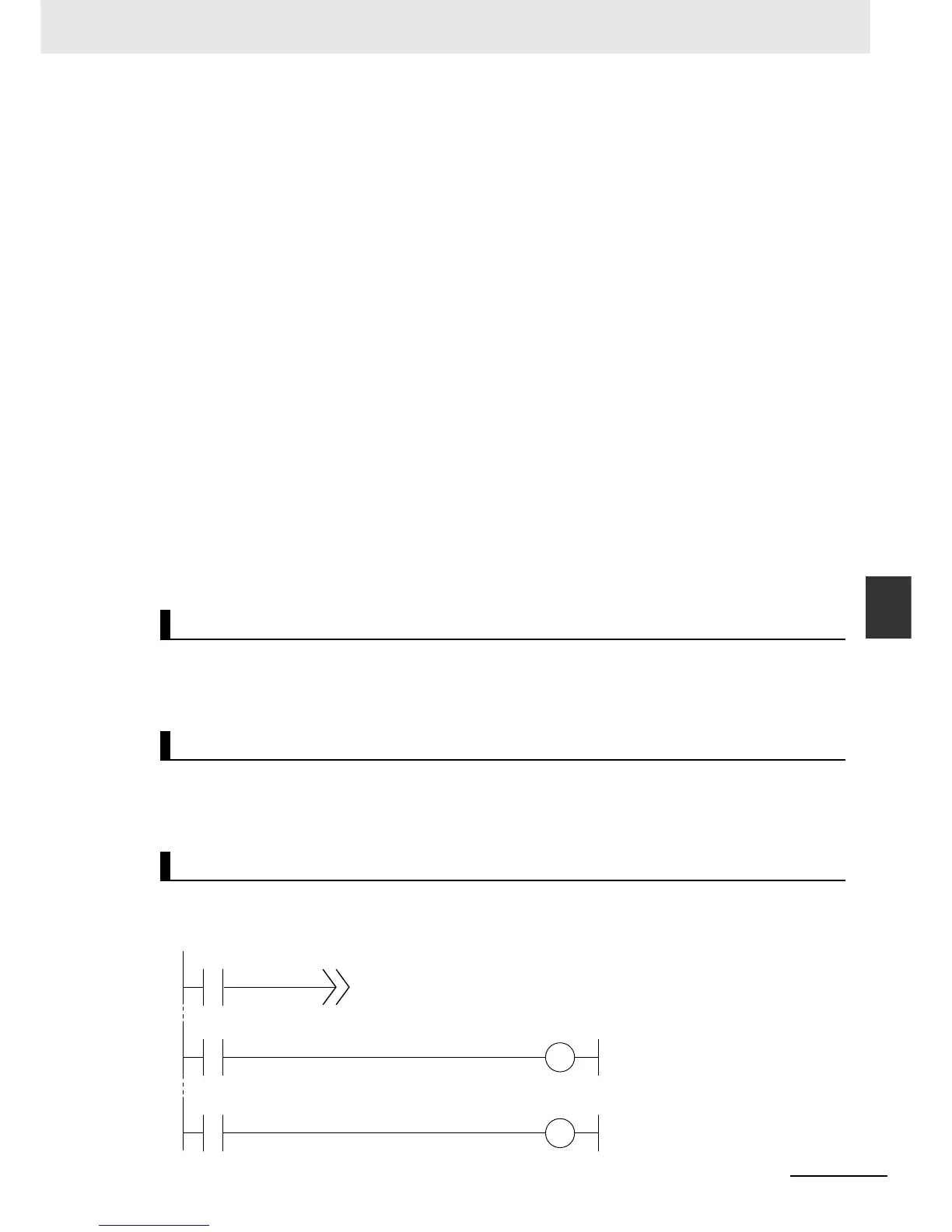
Ladder diagrams are generally executed from top to bottom, but you can use execution control instruc-
tions to change the execution order. In the following example, when the value of program input a
changes to TRUE, execution will move to the point labeled ‘ExceptionProcessing.’
Order of Execution for Ladder Diagrams
Ladder Diagram Completion
Controlling Execution of Ladder Diagrams

 Loading...


