6 Programming
6-74
NJ-series CPU Unit Software User’s Manual (W501)
Connection Configurations
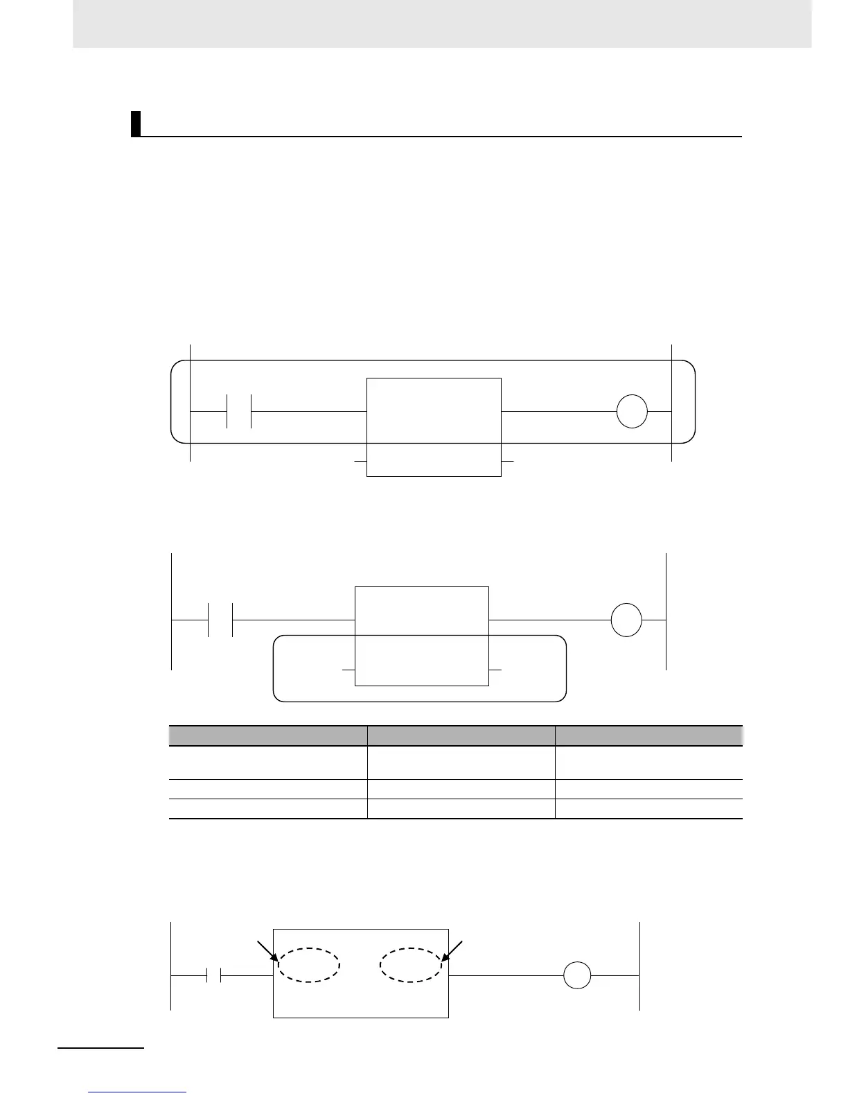
You use the following two types of connections for functions or function blocks.
1) Power Flow Input and Output
In a ladder diagram, the line that connects an input variable of a function or function block and the
left bus bar indicates a BOOL input and the line that connects an output variable to the right bus bar
indicates a BOOL output.
Example:
Inputs are connected in the power flow that connects to the left bus bar. Outputs are connected in
the power flow that connects to the right bus bar.
2) Parameter Inputs and Parameter Outputs
In a ladder diagram, parameter inputs and outputs are specified when the input and output variables
of a function or function block are not connected to the left and right bus bars.
As shown below, you can specify either variables or constants for input and output parameters.
Number of BOOL Variables
At least one BOOL variable each is required for the input and the output (such as EN and ENO) of a
function or function block.
Example:
Connecting Functions and Function Blocks in a Ladder Diagram
Function/function block variables Input parameters Output parameters
Input variables You can specify variables or con-
stants.
---
Output variables --- You can specify only variables.
In-out variables You can specify only variables. You can specify only variables.
y2x2
FB
IN1
IN2
OUT1
OUT2
y2 x1

 Loading...


