6-75
6 Programming
NJ-series CPU Unit Software User’s Manual (W501)
6-5 Programming Languages
6
6-5-2 Ladder Diagram Language
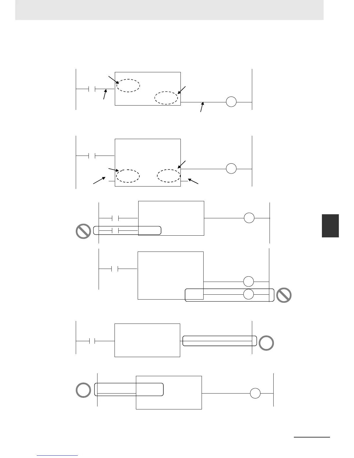
Connections Based on the BOOL Variable Positions
The top BOOL variables are connected to the left and right bus bars. In other words, they become
the power flow input and power flow output.
There is only one power flow input and one power flow output for each function or function block. All
other BOOL variables that are not at the top are for parameter inputs and parameter outputs.
You cannot connect multiple BOOL variables to the left bus bar or the right bus bar as shown below.
You do not have to connect an OUT instruction to the right bus bar. You can connect the function or
function block directly.
A LD instruction is not necessarily required. You can also connect directly to the left bus bar.
MyFB
(BOOL)
IN
(INT)
Val_Out
(INT)
Val_In
(BOOL)
Q
Top BOOL variable
Top BOOL
variable
Power flow
Power flow
MyFB
(BOOL)
IN1
(INT)
Val_Out
(INT)
Val_In
(BOOL)
Q1
(BOOL)
IN2
(BOOL)
Q2
BOOL variable that is not
at the top
Parameter output
b a
Parameter input
BOOL variable
that is not at the
top
RS
(BOOL)
Set
(BOOL)
Q1
(BOOL)
Reset1
MyFB
(BOOL)
IN
(INT)
Val_Out
(INT)
Val_In
(BOOL)
Q1
(BOOL)
Q2
NG
NG

 Loading...


