9-19
9 Backup Functions
NJ-series CPU Unit Software User’s Manual (W501)
9-2 SD Memory Card Backups
9
9-2-2 Restore (SD Memory Card to Controller)
Backing Up Data with the CPU Unit Front-panel DIP Switch
*1 If an SD Memory Card is not inserted, the SD PWR indicator will not light.
The time that is required to restore the data depends on factors such as the CPU Unit, Unit configura-
tion, and user program. Guidelines for the restoration time are given in the following table.
*1 Thirty-two each of the following: R88D-KNA-ECT AC Servo Drives, GX-ID1611 Digital I/O Terminals, and GX-
OD1611 Digital I/O Terminals.
*2 Four CJ1W-SCU22 Serial Communications Units and one CJ1W-EIP21 EtherNet/IP Unit.
*3 Eight each of the following: R88D-KNA-ECT AC Servo Drives, GX-ID1611 Digital I/O Terminals, and GX-
OD1611 Digital I/O Terminals.
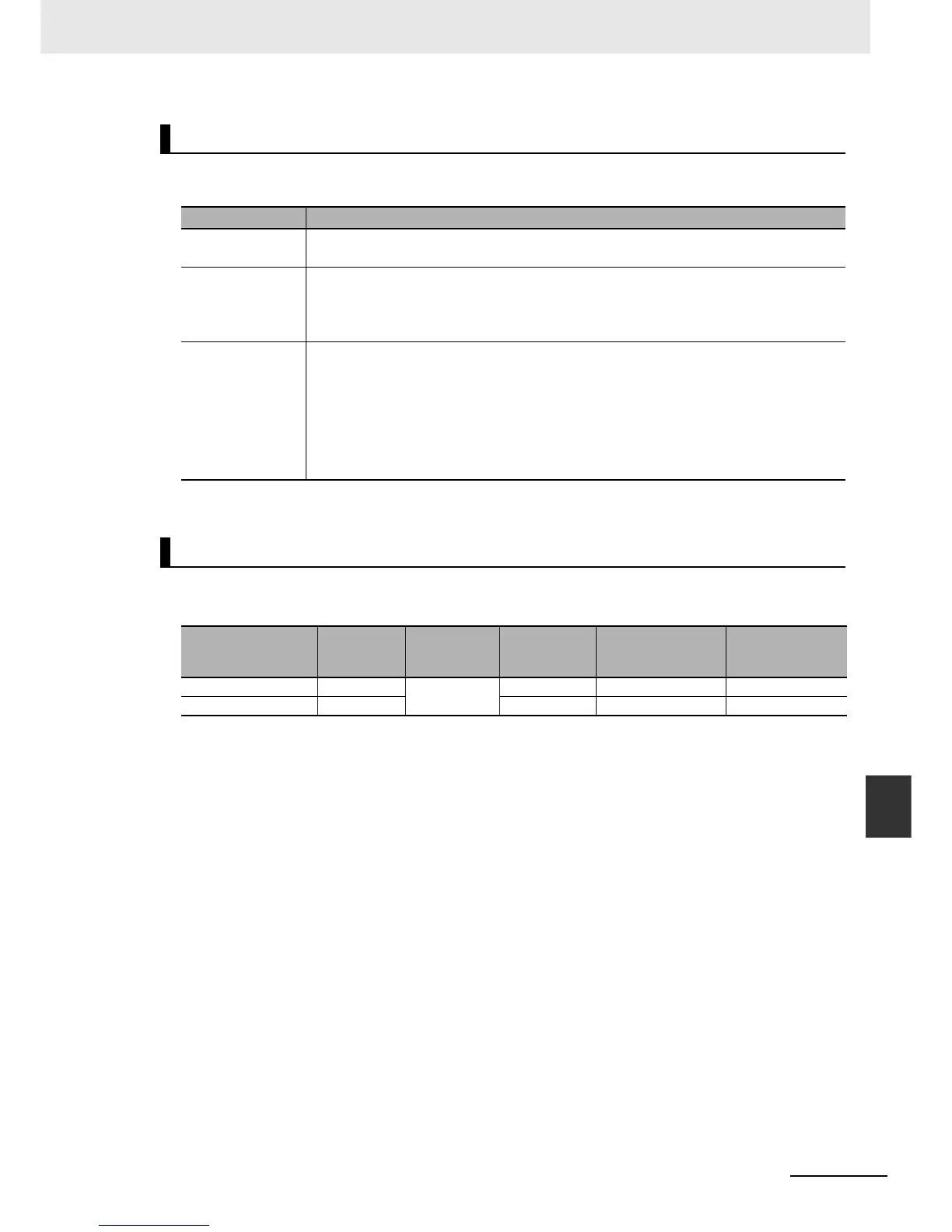
Procedure
Processing stage Procedure
Start command Turn ON the power supply to the Controller with the DIP switch set as follows: 1: OFF, 2:
OFF, 3: ON, and 4: ON.
Executing While Restoring Data
The SD PWR indicator will flash, lighting for 3 seconds and going out for 0.5 seconds. The
RUN indicator will flash, lighting for 0.5 seconds and going out for 0.5 seconds. The SD
BUSY indicator will flash irregularly.
Execution results Normal End:
The SD PWR indicator will light.
Error End:
The SD PWR indicator will flash, lighting for 0.5 seconds and going out for 0.5 seconds.
The indicator stop flashing and stay lit when the SD Memory Card power supply switch is
pressed.
*1
Processing Time
CPU Unit
Connected
EtherCAT
slaves
Connected
CJ-series
Units
Number of
user-defined
POUs
User program
memory size
(Mbytes)
Restoration time
(s)
NJ501- *1 *2 53 2.36 Approx. 100
NJ301- *3 20 0.53 Approx. 70

 Loading...


