15-55
15 Troubleshooting
NJ/NX-series CPU Unit Built-in EtherNet/IP Port User’s Manual (W506)
15-3 Checking Status with the Network Configurator
15
15-3-1 The Network Configurator’s Device Monitor Function
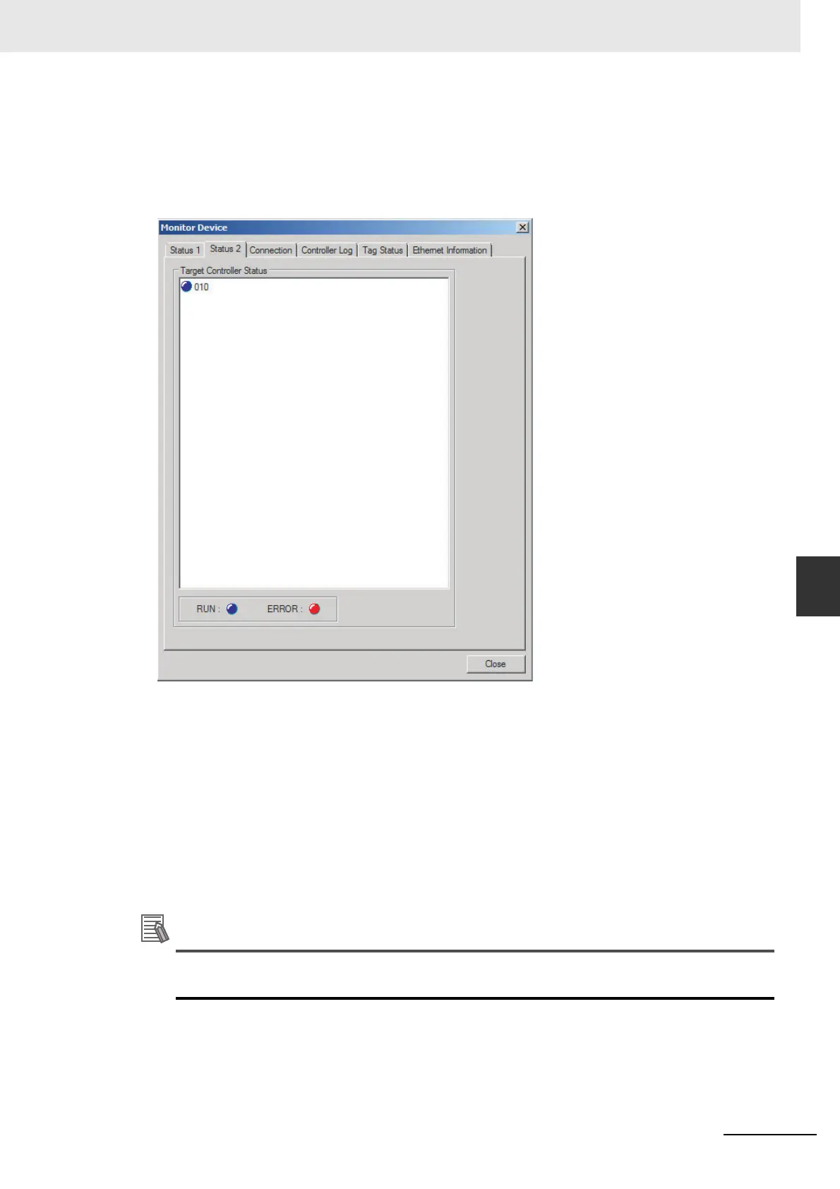
Status 2 Tab Page
This tab page displays information on nodes with tag data link originator settings based on
_EIP_TargetPLCModeSta (Target PLC Operating Mode)
*1
and _EIP_TargetPLCErr (Target PLC
Error Information)
*1
in the _EIP_EstbTargetSta (Normal Target Node Information)
*1
system-defined
variable. This information is in blue if the connection is normal, or red if an error occurred.
*1 These are the system-defined variables for an NJ-series CPU Unit. The system-defined variables for an
NX701 CPU Unit are given below.
CIP Communications 1:
_EIP1_EstbTargetSta (CIP Communications1 Normal Target Node Information)
_EIP1_TargetPLCModeSta (CIP Communications1 Target PLC Operating Mode)
_EIP1_TargetPLCErr (CIP Communications1 Target PLC Error Information)
CIP Communications 2:
_EIP2_EstbTargetSta (CIP Communications2 Normal Target Node Information)
_EIP2_TargetPLCModeSta (CIP Communications2 Target PLC Operating Mode)
_EIP2_TargetPLCErr (CIP Communications2 Target PLC Error Information)
The system-defined variables for an NX1P2 CPU Unit are given below.
_EIP1_EstbTargetSta (CIP Communications1 Normal Target Node Information)
_EIP1_TargetPLCModeSta (CIP Communications1 Target PLC Operating Mode)
_EIP1_TargetPLCErr (CIP Communications1 Target PLC Error Information)
The target Controller status can be used when the Controller status is selected for all the target
sets for both originator and target connections. If it is not selected, it is grayed out on the display.
 Loading...


