6-4
6
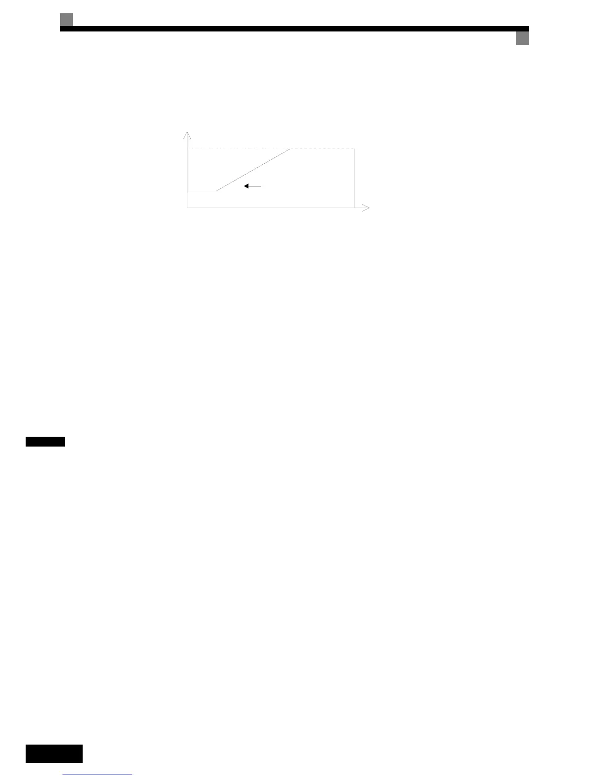
• When using V/f control or V/f control with PG, the carrier frequency can be set to vary depending on the
output frequency, as shown in the following diagram by setting C6-03 (Carrier Frequency Upper Limit),
C6-04 (Carrier Frequency Lower Limit), and C6-05 (Carrier Frequency Proportional Gain).
Fig 6.1 Variable Carrier Frequency
•
With Open Loop and Closed Loop Vector control, the carrier frequency is fixed by the Carrier Frequency
Upper Limit in C6-03 if user-set, or by the carrier frequency set in C6-02.
• To fix the carrier frequency, set C6-03 and C6-04 to the same value, or set C6-05 to 0.
• If the settings are as shown below, OPE11 (Data setting fault) will occur.
If Carrier Frequency Proportional Gain (C6-05) > 6 and C6-03 < C6-04.
If C6-01 = 0 and Carrier Frequency Selection C6-02 is set from 2 to E.
If C6-01 = 1 and Carrier Frequency Selection C6-02 is set from 7 to E.
Carrier Frequency
Output frequency
E1-04
Max. Output Frequency
Output frequency x C6-05 x K*
C6-03
C6-04
*K is the coefficient determined by the set value in C6-03.
C6-03 ≥ 10.0 kHz: K=3
10.0 kHz > C6-03 ≥ 5.0 kHz: K=2
5.0 kHz > C6-03: K=1

 Loading...


