2-26
2
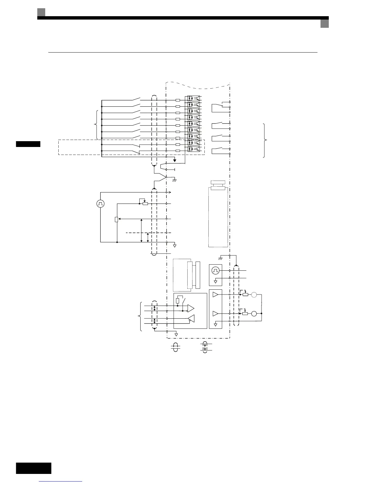
Control Circuit Terminal Connections
Connections to Inverter control circuit terminals are shown in Fig 2.14.
Fig 2.14 Control Circuit Terminal Connections
P
+
+
-
-
Terminating
resistance
BB
BB1
IG
MEMOBUS
communication
RS-485/422
P
P
R+
R-
S+
S-
Shielded
wires
Twisted-pair
shielded wires
Analog input setting
adjustment
2 k
Ω
0 to 10 V
2 k
Ω
4 to 20 mA
PP
Pulse train input [Default:
Frequency reference input]
0 to 32 kHz
Analog input power supply
15 V, 20 mA
Analog input 1: Master
frequency reference
0 to 10 V (20 k
Ω)
Multi-function analog input 2
[Default: Frequency bias
4 to 20 mA (20 k
Ω)]
0 V
Analog input power supply
-15 V, 20 mA
RP
+V
A1
A2
AC
-V
FM
AM
AC
AM
FM
AC
MP
Adjustment,
20 k
Ω
Adjustment,
20 k
Ω
Multi-function analog output 2
(-10 to +10 V, 2 mA / 4 to 20 mA)
[Default: Output current, 0 to 10 V)
4 to 20 mA (20 k
Ω)]
Multi-function analog output 1
(-10 to +10 V, 2 mA / 4 to 20 mA)
[Default: Output frequency, 0 to 10 V)
4 to 20 mA (20 k
Ω)]
Pulse train output
0 to 32 kHz (2.20 k
Ω)
[Default: Output frequency]
E(G)
Shield
terminal
Forward Run / Stop
Reverse Run / Stop
External Fault
Fault reset
Multi-step speed setting 1
Multi-step speed setting 2
Jog frequency selection
Multi-function
digital inputs
[Factory setting]
S1
S2
S3
S4
S5
S6
S7
SN
SC
SP
24 V
E(G)
Shield
terminal
MA
MB
MC
M1
M2
M3
M4
M5
M6
Multi-function digital output
250 VAC, 1 A max.
30 VDC, 1 A max.
Fault relay output
250 VAC, 1 A max.
30 VDC, 1 A max.
Relay output 1
[Default: Running]
Relay output 2
[Default: Zero speed]
Relay output 3
[Default:
Frequency agree 1]
2CN
PG
Option
Card
2CN
Input
Option
Card
Hardware Baseblock
Hardware Baseblock 1
Hardware Baseblock Terminals
are only available in the Inverter
Version with Safety

 Loading...


