6-98
6
Using the Timer Function
The multi-function digital input terminals S3 to S7 can be used as timer function input terminals, and multi-
function output terminals M1-M2, M3-M4, and M5-M6 can be used as timer function output terminals. By
setting the delay time, you can prevent chattering of the sensors and switches.
• Set one of the parameters H1-01 to H1-05 (digital input terminal S3 to S7) to 18 (timer function input).
• Set H2-01 to H2-03 (multi-function output terminals M1-M2, M3-M4, and M5-M6 function selection) to
12 (timer function output).
Related Parameters
Multi-function Digital Inputs (H1-01 to H1-05)
Multifunction Outputs (H2-01 to H2-03)
Setting Example
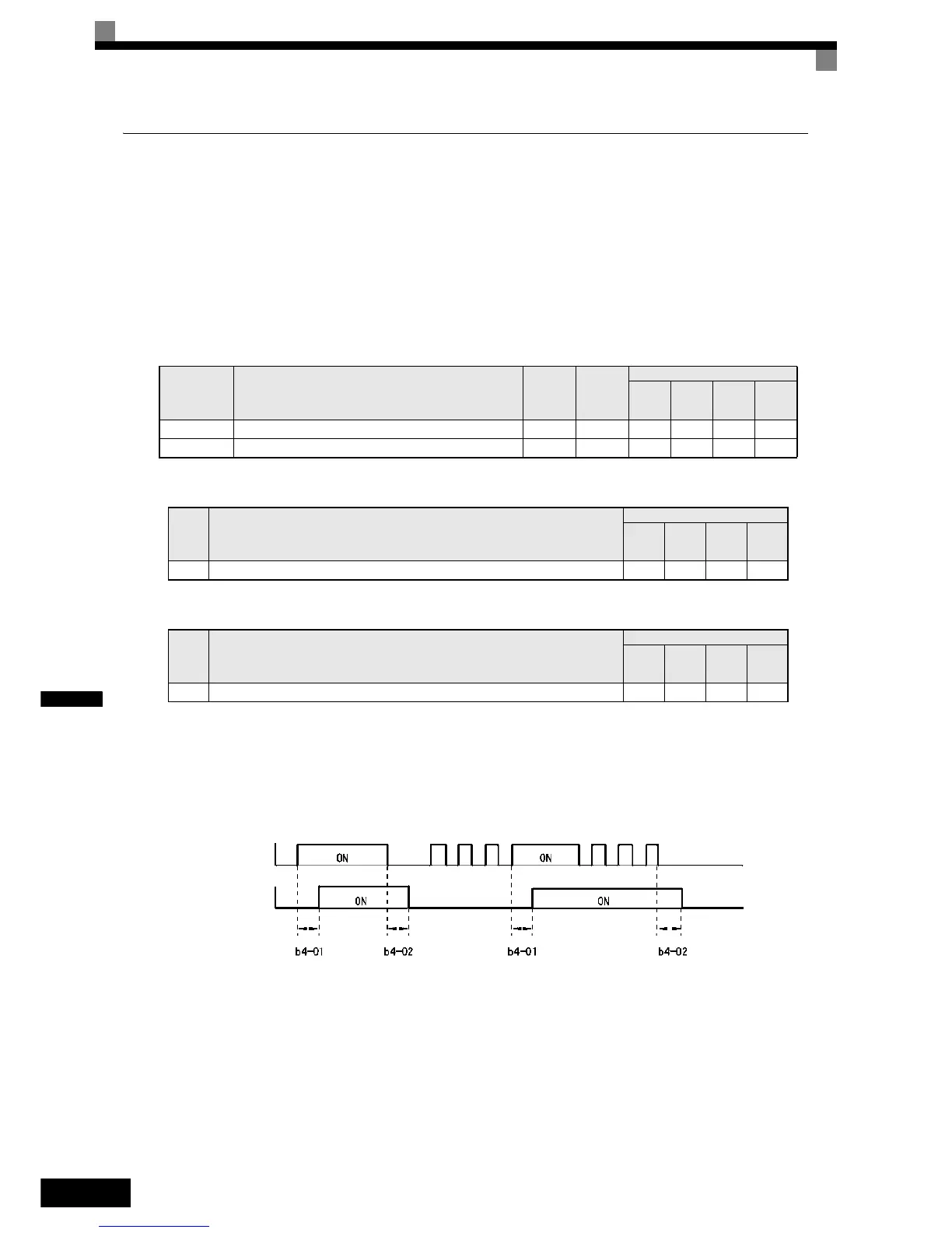
When the timer function input ON time is longer than the value set in b4-01, the timer output function is
turned ON. When the timer function input OFF time is longer than the value set in b4-02, the timer output
function is turned OFF. An example of timer function operation is given in the following diagram.
Fig 6.79 Timer Function Operation Example
Parameter
No.
Name
Factory
Setting
Change
during
Opera-
tion
Control Methods
V/f
V/f with
PG
Open
Loop
Vector
Closed
Loop
Vector
b4-01 Timer function ON-delay time 0.0 s No A A A A
b4-02 Timer function OFF-delay time 0.0 s No A A A A
Set
Value
Function
Control Methods
V/f
V/f
with
PG
Open
Loop
Vector
Closed
Loop
Vector
18 Timer function input Yes Ye s Yes Ye s
Set
Value
Function
Control Methods
V/f
V/f
with
PG
Open
Loop
Vector
Closed
Loop
Vector
12 Timer function output Yes Yes Ye s Ye s
Timer function input
Timer function output

 Loading...


