4-2
4
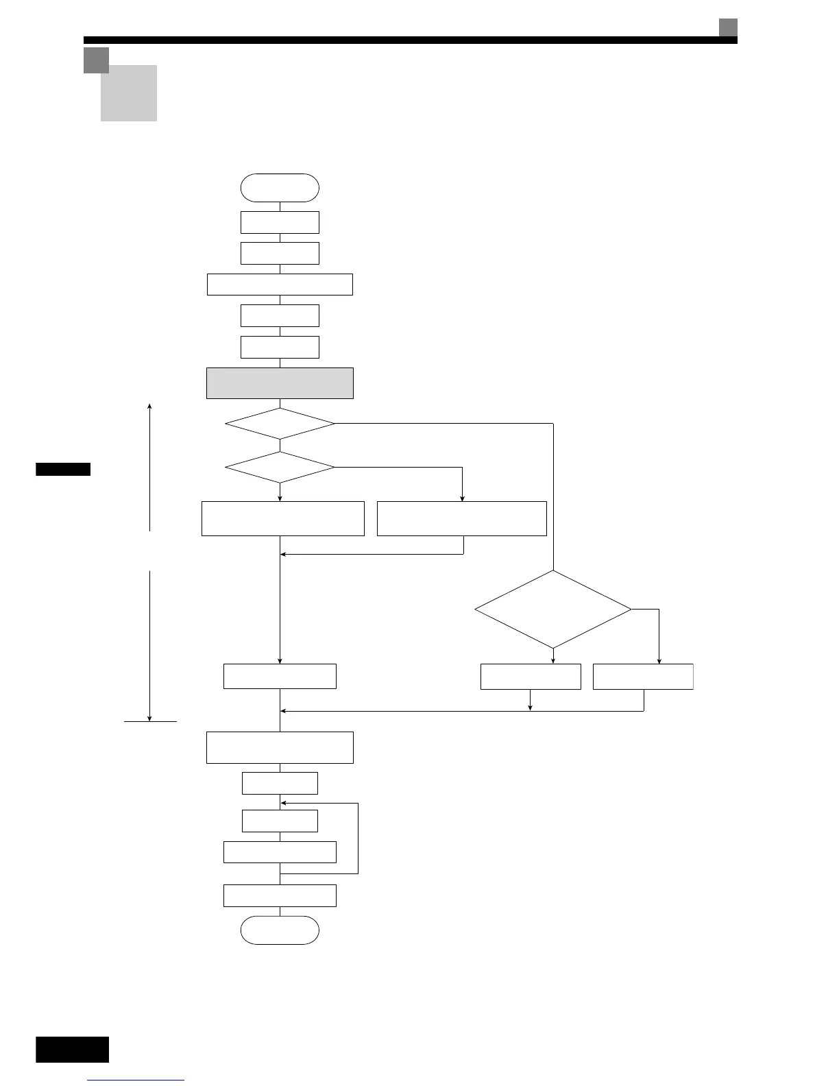
Trial Operation Procedure
Perform trial operation according to the following flowchart. When setting the basic parameters, always set
C6-01 (Heavy/Normal Duty Selection) according to the application.
Fig 4.1 Trial Operation Flowchart
V/f Control with PG (A1-02=1)
START
Installation
Wiring
Turn ON power.
Confirm status.
Basic settings
(Quick programming mode)
Set power supply voltage jumper.
Select operating
method.
Settings according
to control mode
Application settings
(Advanced programming mode)
No-load operation
Loaded operation
Optimum adjustments and
parameter settings
Check/record parameters.
END
YES
V/f control
Vector Control (A1-02=2 or 3)*5
Set E1-03.
V/f default: 200V/50Hz(400V/50Hz)
Set E1-03, E2-04, and F1-01.
V/f default: 200V/50Hz (400V/50Hz)
YES
NO
V/f control?
PG?
Motor operation during
autotuning possible?
Non-rotating autotuning
for line-to-line resistance
Rotating
autotuning
Non-rotating
autotuning
*3
*4
*2
*1
*6
*6
NO
NO
YES
1. Set for 400 V Class Inverter for 75 kW or more.
2. If there is a reduction gear between the motor and PG, set the
reduction ratio in F1-12 and F1-13 in advanced programming
mode.
3. Use rotational autotuning to increase autotuning accuracy when-
ever it is okay for the motor to be operated.
4. If the motor cable changes to 50 m or longer for the actual instal-
lation, perform non-rotating autotuning for the line-to-line resis-
tance only on site.
5. The default control mode is Open Loop Vector control
(A1-02=2).
6. If the maximum output frequency and the base frequency are dif-
ferent, set the maximum output frequency (E1-04) after autotun-
ing.

 Loading...


