6-122
6
Torque Control Operation
In torque control a torque value can be given as reference for the motor output. If the torque command and the
load are not balanced, the motor accelerates or decelerates.
The speed limit circuit prevents the motor speed from rising above certain value set by an analog input or
parameter d5-04. The speed limit function mainly consists of two parts, the priority circuit and the speed
limiter circuit.
The priority circuit selects between the torque reference value from the analog input or from the speed control-
ler (ASR) output. If the output speed is below the speed limit, the analog input value is taken as torque refer-
ence. Otherwise the ASR output value is taken as torque reference.
The speed limit circuit adds a speed suppressing torque to the torque output if the speed exceeds the speed
limit. Together with the priority circuit it prevents the output speed from exceeding the speed limit.
For a further adjustment of the torque reference value a torque compensation can be input, either by a third
analog input (if the AI-14B analog option card is used) or in combination with a speed limit by parameter by
analog input terminal A1. The torque compensation can be used for a dancer control in winding application.
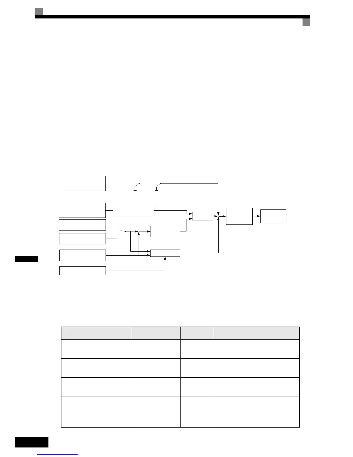
The torque control block diagram is shown in Fig 6.86.
Fig 6.86 Torque Control Block Diagram
Inputting Torque References and Torque Reference Directions
The torque reference can be input using an analog voltage or current signals. The torque reference input meth-
ods are listed in the table below.
Torque Reference Input
Method
Reference Location
Selection
Method
Remarks
Voltage input (0 to 10 V)
Analog input A2
(Turn OFF pin 2 of
SW1.)
d5-01 = 1
H3-08 = 0
H3-09 = 13
To switch the torque reference between
positive and negative torque, use a digital
input (H1- = 78).
Voltage input (-10 to +10 V)
Analog input A2
(Turn OFF pin 2 of
SW1.)
d5-01 = 1
H3-08 = 1
H3-09 = 13
The torque reference direction is switched
with the analog input voltage direction.
Current input (4 to 20 mA)
Analog input A2
(Turn ON pin 2 of
SW1.)
d5-01 = 1
H3-08 = 2
H3-09 = 13
To switch the torque reference between
positive and negative torque, use a digital
input (H1- = 78).
Option Card (AI-14B)
(0 to
±10 V)
Channel 2
b1-01=1
d5-01 = 1
F2-01 = 0
H3-08 = 1
H3-09 = 13
Channel 2 of the AI-14B card replaces
analog input A2
-
+
+
+
+
d5-03
1
2
d5-01
d5-03
0, 1 1
22
Torque reference from
analog input A2
(H3-09=13)
Speed limit from analog
input A1
Speed limit in parameter
d5-04
Speed
Feedback
Speed limit bias
d5-05
Torque reference filter
time d5-02
Speed limiter
Speed controller
(ASR)
Priority
Circuit
Torque limits
(L7-
)
Internal Torque
Reference
Torque compensation from
analog input A1

 Loading...


