6-81
6
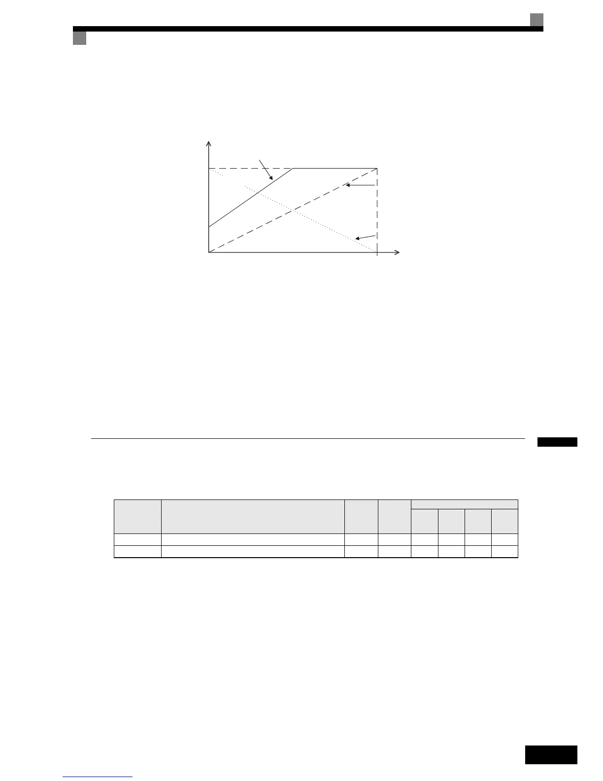
Adjustment Examples
The influence of the settings of gain and bias on the analog output channel is shown on three examples in Fig
6.74.
Fig 6.74 Monitor Output Adjustment
Switching Analog Monitor Signal Levels
The values of some monitor items can be both, positive or negative. If these items shall be output at an analog
output, the signal level should be set to –10V to +10V (H4-07/08 = 1). Negative values will be output as neg-
ative voltage (–10V to 0) and positive values will be output as positive voltage (0 to +10V).
For monitor items that can have positive or negative values please refer to page 5-70, Status Monitor Parame-
ters: U1.
Both analog outputs can create a 4-20 mA current signal as well. Therefore the parameters H4-07 and H4-08
have to be set to 2. Additionally the jumper CN15 has to be set to current output for each channel. Refer to
page 2-24, Jumper CN15 and DIP Switch S1 for details about the jumper setting.
Using the Pulse Train Monitor Output
Related Parameters
Selecting Pulse Monitor Items
Some of the digital operator monitor items (U1- [status monitor]) can be output at pulse monitor terminal
MP-AC. Refer to page 5-70, Status Monitor Parameters: U1 and set the
part of U1- (Status monitor)
for H6-06.
Adjusting the Pulse Monitor Items
To adjust the pulse frequency output scaling, set the pulse output frequency which is equal to 100% of the
monitor item in parameter H6-07.
Set H6-06 to 2, and H6-07 to 0, to output the frequency synchronous with the Inverter's U-phase output fre-
quency.
Parameter
No.
Name
Factory
Setting
Change
during
Opera-
tion
Control Methods
V/f
V/f with
PG
Open
Loop
Vector
Closed
Loop
Vector
H6-06Pulse train monitor selection 2 Yes AAAA
H6-07 Pulse train monitor scaling 1440 Hz Yes AAAA
0V
10V
100%
Gain: 100%
Bias: 0%
Gain: 170%
Bias: 30%
Gain: 0%
Bias: 100%
Monitor item
(e.g. Output Frequency)
Output voltage/
current
3V/8.8mA

 Loading...


