6-69
6
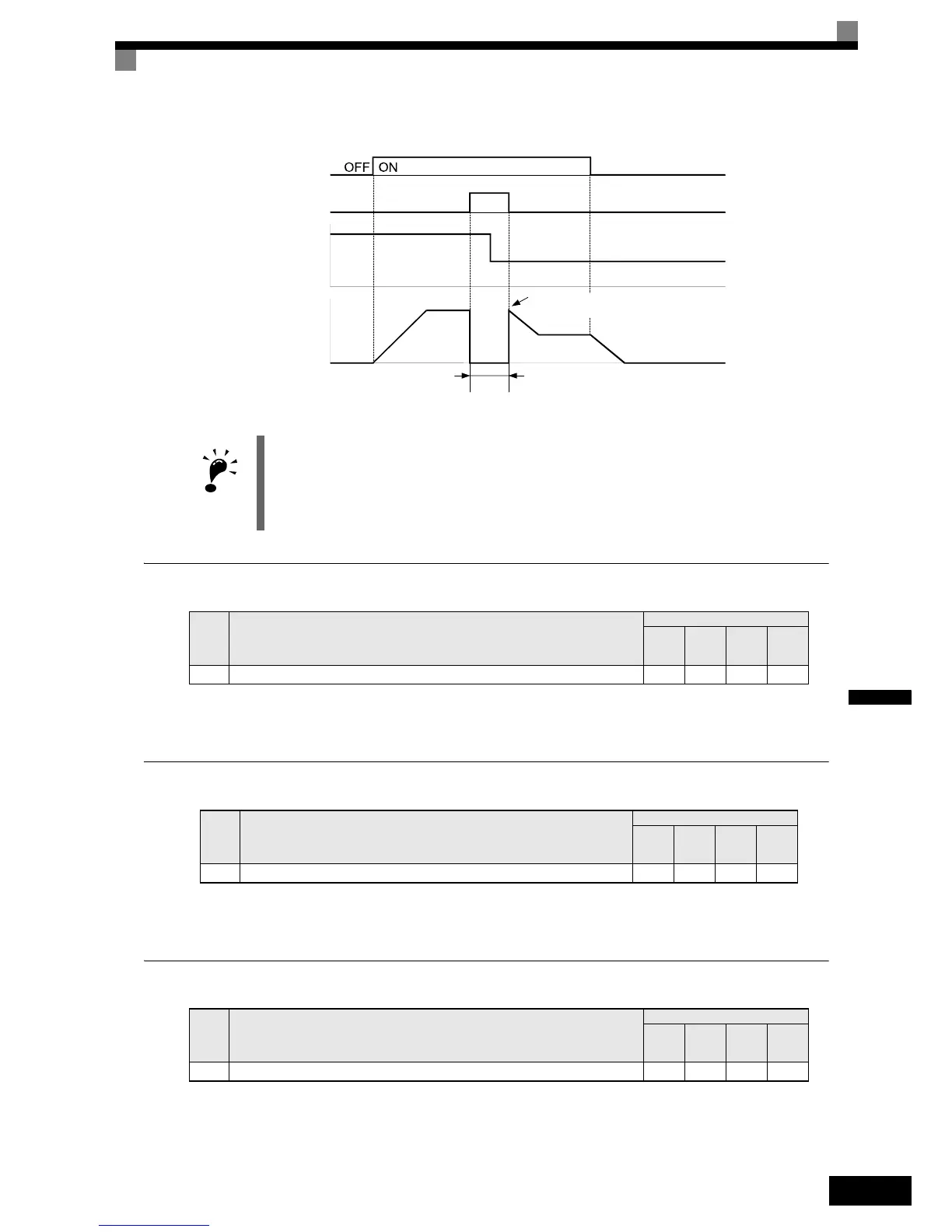
The timing chart when using a baseblock command is shown in Fig 6.67.
Fig 6.67 Baseblock Commands
OH2 (Overheat) Alarm Signal Input
If a digital input is programmed for this function (H1-=B) an OH2 alarm message can be displayed on the
display by turning this input to ON. The fault ouput will not be operated.
Multifunction Analog Input A2 Disable/Enable
If a digital input is programmed for this function (H1-=C) the analog input A2 can be enabled or disabled
by switching the digital input ON/OFF (ON – Analog Input A2 enabled).
Drive Enable/Disable
If a digital input is programmed for this function (H1-=6A) the drive can be enabled or disabled by
switching the digital input ON/OFF (ON – Drive enabled).
IMPORTANT
When a contactor between inverter and motor is used, always perform a base block command before
opening the contactor.
Set
Value
Function
Control Methods
V/f
V/f
with
PG
Open
Loop
Vector
Closed
Loop
Vector
B OH2 Alarm input (ON: OH2 is displayed) Yes Yes Yes Yes
Set
Value
Function
Control Methods
V/f
V/f
with
PG
Open
Loop
Vector
Closed
Loop
Vector
C Analog Input A2 enable/disable (ON: Enable) Yes Yes Yes Yes
Set
Value
Function
Control Methods
V/f
V/f
with
PG
Open
Loop
Vector
Closed
Loop
Vector
6A Enable/Disable drive (ON: drive enabled) Yes Yes Yes Yes
Forward operation/Stop
Baseblock command
Input
Cleared
Frequency reference
Output frequency
Coast to a stop
Speed search or operation with the previous
frequency reference

 Loading...


