2-23
2
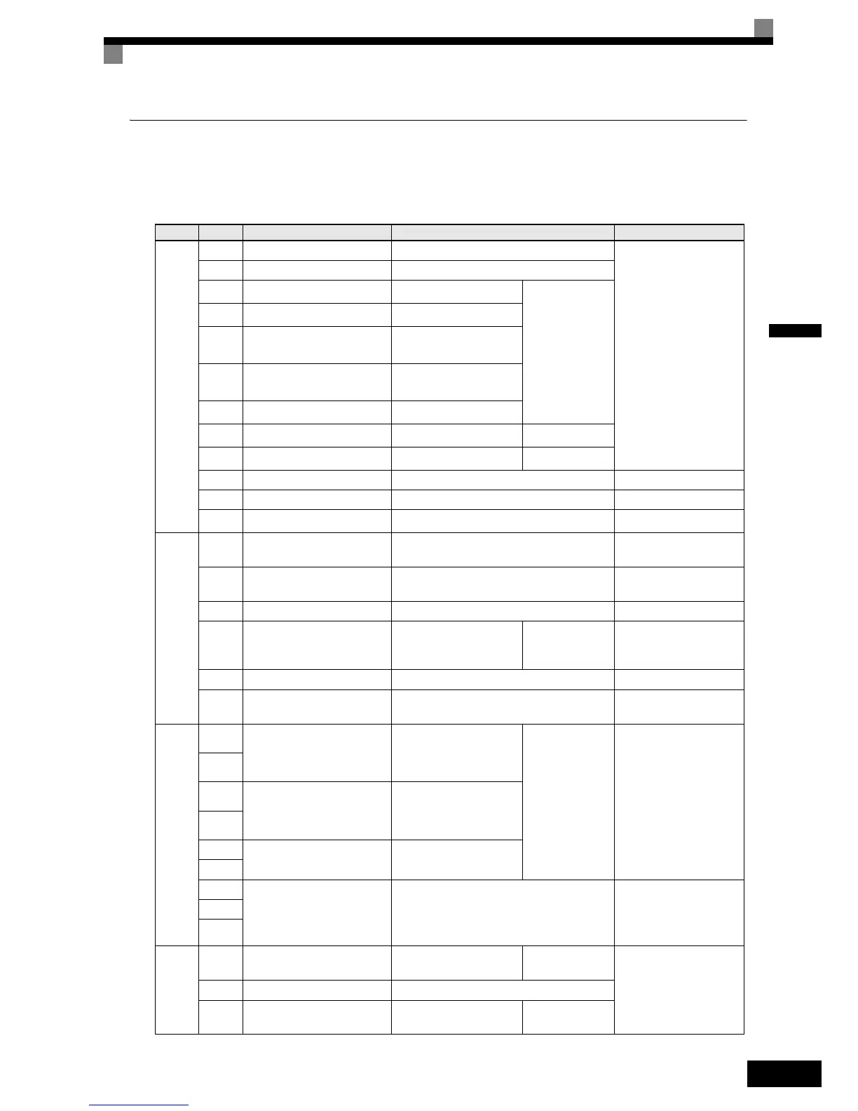
Control Circuit Terminal Functions
The functions of the control circuit terminals are shown in Table 2.9. Use the appropriate terminals for the cor-
rect purposes.
Table 2.9 Control Circuit Terminals with Default Settings
Type No. Signal Name Function Signal Level
Digital
input
signals
S1 Forward run/stop command Forward run when ON; stopped when OFF.
24 VDC, 8 mA
Photocoupler
S2 Reverse run/stop command Reverse run when ON; stopped when OFF.
S3
External fault input
*1
Fault when ON.
Functions are
selected by set-
ting H1-01 to
H1-05.
S4
Fault reset
*1
Reset when ON
S5
Multi-step speed reference
1
*1
(Master/auxiliary switch)
Auxiliary frequency ref-
erence when ON.
S6
Multi-step speed reference
2
*1
Multi-step setting 2 when
ON.
S7
Jog frequency reference
*1
Jog frequency when ON.
BB
Hardware Baseblock
*2
––
BB1
Hardware Baseblock 1
*2
––
SC Digital input common
––
SN Digital Input Neutral
––
SP Digital Input Power Supply +24VDC power supply for digital inputs
24 VDC, 250 mA max.
*3
Analog
input
signals
+V 15 V power output 15 V power supply for analog references
15 V
(Max. current: 20 mA)
–V –15 V power output –15 V power supply for analog references
–15 V
(Max. current: 20 mA)
A1 Frequency reference –10 to +10 V/100% –10 to +10 V(20 kΩ)
A2 Multi-function analog input
4 to 20 mA/100%
–10 V to +10 V/100%
Function is
selected by set-
ting H3-09.
4 to 20 mA(250Ω)
–10 V to +10 V(20kΩ)
AC Analog reference common – –
E(G)
Shield wire, optional ground
line connection point
––
Se-
quence
output
signals
M1
Running signal
(1NO contact)
Operating when ON.
Multi-function
digital outputs
Relay contacts
Contact capacity:
1 A max. at 250 VAC
1 A max. at 30 VDC
*4
M2
M3
Zero speed
Zero level (b2-01) or
below when ON
M4
M5
Speed agreement detection
Within ±2 Hz of set fre-
quency when ON.
M6
MA
Fault output signal
Fault when CLOSED across MA and MC
Fault when OPEN across MB and MC
Relay contacts
Contact capacity:
1 A max. at 250 VAC
1 A max. at 30 VDC
*4
MB
MC
Analog
output
signals
FM
Multi-function analog output
(frequency output)
0 to 10 V, 10V=100%
output frequency
Multi-function
analog output 1
–10 to +10 V max. ±5%
2 mA max.
4 to 20 mA current output
AC Analog common –
AM
Multi-function analog output
(current monitor)
0 to 10 V, 10V=200%
Inverter's rated current
Multi-function
analog output 2

 Loading...


