2-24
2
* 1. The default settings are given for terminals S3 to S7. For a 3-wire sequence, the default settings are a 3-wire sequence for S5, multi-step speed setting 1
for S6 and multi-step speed setting 2 for S7.
* 2. Terminals BB and BB1 are only available in the Inverter version with Safety.
* 3. Do not use this power supply for supplying any external equipment.
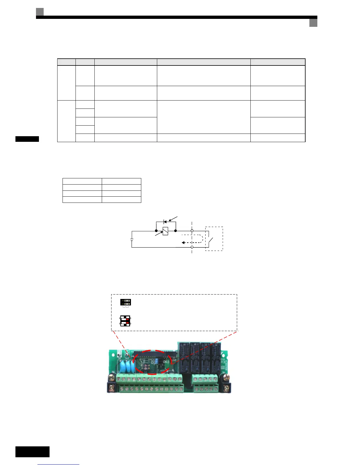
* 4. When driving a reactive load, such as a relay coil with DC power supply, always insert a flywheel diode as shown in
Fig 2.12.
* 5. Pulse input specifications are given in the following table.
Fig 2.12 Flywheel Diode Connection
Jumper CN15 and DIP Switch S1
The jumper CN 15 and DIP switch S1 are described in this section.
Fig 2.13 Jumper CN15 and DIP Switch S1
Pulse I/O
RP
Pulse input
*5
H6-01 (Frequency reference input)
0 to 32 kHz (3 kΩ)
High level voltage 3.5 to
13.2 V
MP Pulse monitor H6-06 (Output frequency)
0 to 32 kHz
+15 V output (2.2 kΩ)
RS-485/
422
R+
MEMOBUS communica-
tions input
For 2-wire RS-485, short R+ and S+ as well
as R- and S-.
Differential input, Photo-
coupler isolation
R-
S+
MEMOBUS communica-
tions output
Differential input, Photo-
coupler isolation
S-
IG Signal common – –
Low level voltage 0.0 to 0.8 V
High level voltage 3.5 to 13.2 V
H duty 30% to 70%
Pulse frequency 0 to 32 kHz
Table 2.9 Control Circuit Terminals with Default Settings
Type No. Signal Name Function Signal Level
External power:
30 VDC max.
Coil
Flywheel diode
1 A max.
The rating of the flywheel diode
must be at least as high as the cir-
cuit voltage.
S1
CN15
Ch1
Ch2
VI
Off On
V I
RS422/485 Port Termination Resistance
Analog Input A2 Current/Voltage Signal Selection
Analog Output FM Current/Voltage Signal Selection
Analog Output AM Current/Voltage Signal Selection

 Loading...


