1-7
1
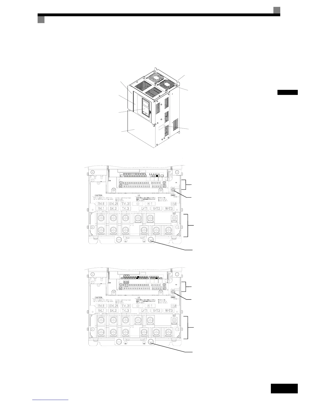
Inverters of 22 kW or More
The external appearance and component names of the Inverter are shown in Fig 1.6. The Inverter with the ter-
minal cover removed is shown in Fig 1.7
Fig 1.6 Inverter Appearance (22 kW or More)
Fig 1.7 Terminal Arrangement of Standard Inverter (22 kW or More)
Fig 1.8 Terminal Arrangement of Safety Inverter (22 kW or More)
Mounting holes
Cooling fan
Nameplate
Inverter cover
Front cover
Digital Operator
Terminal cover
$&
$&6
9
$0
5 053$&
6 6
63
6 0
9
6
6&
,*
$
0
61 0
)0
$
( *
( *
0&0%
6 0
03 0$
06 6
5
6
Control Circuit Terminals
Main Circuit Terminals
Charge Indicator
Ground Terminals
E(G) S1 S2 S3 S4 S5 S6 S7 FM AC AM IG S+ S-
SN SC SP A1 A2 V+ AC V- MP AC RP R+ R-
M3 M4 M1 M2
M5 M6 MA MB MC
E(G)
BB BB1 SC
Control Circuit Terminals
Main Circuit Terminals
Charge Indicator
Ground Terminals

 Loading...


