2-4
2
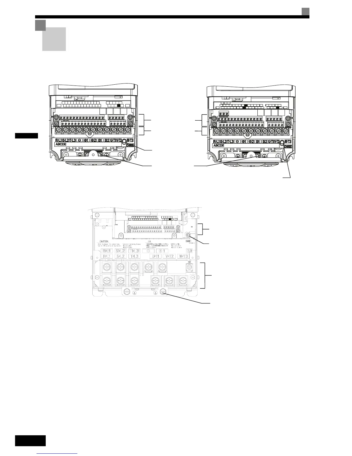
Terminal Block Configuration
The terminal arrangements are shown in Fig 2.2 and Fig 2.3.
Fig 2.2 Terminal Arrangement of Standard and Safety Inverter (200 V/400 V Class Inverter of 0.4 kW)
Fig 2.3 Terminal Arrangement of Standard Inverter (200 V/400 V Class Inverter of 22 kW or more)
$&
6
9 0
6 6
63
6 0
9
6
6& $
0
61 0$
(*
(*
0&0%
6 0
0$
06
$& $0
553$&
,*)0
03
6
5
6
E(G) S1 S2 S3 S4 S5 S6 S7 FM AC AM IG S+ S-
SN SC SP A1 A2 V+ AC V- MP AC RP R+ R-
M3 M4 M1 M2
M5 M6 MA MB MC
E( G)
BB BB1 SC
Control Circuit Terminals
Main Circuit Terminals
Charge Indicator
Ground Terminals
Charge Indicator
Standard Inverter
Safety Inverter
$&
$&6
9
$0
5 053$&
6 6
63
6 0
9
6
6&
,*
$
0
61 0
)0
$
( *
( *
0&0%
6 0
03 0$
06 6
5
6
Control Circuit Terminals
Main Circuit Terminals
Charge Indicator
Ground Terminals

 Loading...


